Pardon me if I have it wrong, but I thought the "twisting" motion was produced by currents internal to the plasma, and not a product of the external magnets. If so what then keeps the internal current stable and in the "center".Art Carlson wrote:Concerning questions from several authors about tokamak physics:
The radial electric field in a tokamak is a very important parameter that is thought to influence the confinement by up to a factor of two. What's important is actually the gradient in the field (the curvature in the potential). The picture is that the EXB drift is then dependent on radius and tears convective cells apart before they can get very big. Unfortunately, the plasma pretty much chooses its own potential profile, and there is very little that can be done about it from the outside. One thing that influences it is fast ions from neutral injection that are lost quickly when they are on certain orbits.
An essential feature of a tokamak is that the field is not uniform, but it twists as it goes around the torus. The field lines sort themselves into flux surfaces. The particles tend to stick to these surfaces, and that is how they know where the center is.
Carlson and Nebel
Carter
-
Art Carlson
- Posts: 794
- Joined: Tue Jun 24, 2008 7:56 am
- Location: Munich, Germany
Yes, the twisting in a tokamak comes from internal currents. (In a stellarator it comes from the external coils.) But the current doesn't have to be in the center. Even if it was uniform or had a wierd profile, there would be some position near the center where the field it produces would vanish. Over and above that, because of conduction losses to the edge and the fact that many heat sources are centrally peaked, the temperature is higher in the middle, so the resistivity is lower there. This leads leads naturally to a peaked current profile (which is not necessarily a good thing in a tokamak).kcdodd wrote:Pardon me if I have it wrong, but I thought the "twisting" motion was produced by currents internal to the plasma, and not a product of the external magnets. If so what then keeps the internal current stable and in the "center".
I guess "centered" and not "in the center" is what I meant; as in off-center would lead it toward the wall. That's kind of how I was thinking. But if the losses to the wall are what keep the plasma stable then it seems like attempts to improve confinement (decrease loss to walls) would actually decrease that stability, which could ultimately leading to confinement problems.
Carter
Hello Indrek,
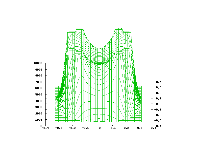
That looks nice. Can you tell me what the axes represent? I assume the "floor" represents x and y as a cross-section through the coil centres and the polywell centre, and I assume the height represents magnetic field (or perhaps electron density? or something else).
When you say the "flawed" potential well, what exactly do you mean? Useless? Some factors were not accounted for? Some assumptions were made?
Thanks in advance!
Regards,
Tony Barry
You assume correctly about the x and y. The z axis represents the potential. 0 (ground) up to +10KV (the coils).
Flawed in a sense that the effective well depth is almost nonexistent - ions can escape through the faces at already very low energies - no matter that the voltage is quite low in the middle compared to the coils. So the voltage in the middle drops but we can't use it to fuse ions.
The idea of polywell is that a dip forms in the middle where we can put ions (marbles for this picture, think no friction but gravity) to oscillate up and down - until they collide and fuse.
Not that my simulation was any good. But I think it was good enough so that this flaw is a possibility.
- Indrek
Hello Indrek,
Thank you for your speedy reply. Much appreciated. I gather from your note, and the rest of this thread that I have been re-reading since I posted the previous comment, that your simulation included the effect of electrons circulating in the polywell; and the result you present is the electrostatic gradient across the polywell's orthogonal plane.
I see that there is a minimal well forming from your images. I presume that if correct, this would not be deep enough to contain ions.
Therefore the simulation should be checked for correctness before we disband Talk-Polywell and return to our former pursuits ...
Is there a way to check for correctness?
Regards,
Tony Barry
(edit) and if correct, can we reduce the radius of the magrid coils to reduce the leak?
My previous post got me to thinking ... what is the diameter ratio for a polywell coil in an orthogonal setting such that:-
the radius from the centre of the coil to the inner coil surface
is the same as
the distance from the coil outer surface
to the corner cusp
?
By using such a ratio, the leakage from the centre cusp would be the same as the leakage from the corner cusp. thus maximising the well depth.
We specify two items ... coil section diameter, and distance between facing coil centres.
A nice challenge for a person well versed in solid geometry.
Regards,
Tony Barry
That plot is bothering me quit a bit. The electric potential from a ring of charge is kQ/sqrt(z^2 + r^2) where z is distance along the axis and r is the radius of the circle. Even taking the limit where z >> r then it should decay at no more then 1/z (point charge approximation). Maybe it's just scale or perspective but it looks like it is decaying too quickly. Indrek, could you do a favor and make the same plot but without the effect of the electrons?
Carter
Without the electrons? As in without the potential well - just a plain system with no charges?
You can see them here, well not really 3D plots but 2D color-maps (color/elevation - same thing - potential):
http://www.mare.ee/indrek/ephi/pef8/
Note: the charge within the polywell in that page is an idealization. In simulation it is somewhat bigger and distribution is different. Also in simulation we have the beams through the faces.
- Indrek
edit: one thing affecting this a bit is also that I put the grounded grid very close to the coils
There are too many unknowns about what your plot is showing. Is the potential well depth always going to be that small or are we just seeing a very low electron density. What happens when you put 10x more electrons inside. The inter electron repulsion isn't very great because as you said the well depth is tiny so surly we can let more in. Also, about the faces, does the well depth have a great affect on the potential "hole". It's hard, at least for me, to tell that in 2D. And as you said they're not even the same simulation? Maybe also a 3D plot of electron density would be helpful.
Carter
Wonderful picture as usual. Very easy to visualize.Indrek wrote:Flawed in a sense that the effective well depth is almost nonexistent - ions can escape through the faces at already very low energies - no matter that the voltage is quite low in the middle compared to the coils. So the voltage in the middle drops but we can't use it to fuse ions.
- Indrek
In addition to being shallow, the well is fairly wide. This is probably due to the fact that the electrons repeal each other. The ions will not be attracted to a point in the center, but will wonder aimlessly in a large volume. So much for annealing and head on collisions.
Fusion is easy, but break even is horrendous.
With all due respect to Indrek, we must firstly establish the correctness of this model before making decisions based on it. Indrek's work relies wholly on numerical simulation and not on experimental results, therefore it is within the realm where people remote from the site may do useful checking.
I for one would be happy to put my efforts into checking the results, although I cannot really comment on the underlying equations.
Regards,
Tony Barry
I for one would be happy to put my efforts into checking the results, although I cannot really comment on the underlying equations.
Regards,
Tony Barry
Actually, that image looks just about right for a parabolic potential well. Remember that the electric field is the (negative) gradient of the potential, which within that bowl is always pointed towards the centre. If a high-density, high-beta wiffleball can solve the shallowness of the well (which I expect it can), this should work like it's supposed to.pstudier wrote:The ions will not be attracted to a point in the center, but will wonder aimlessly in a large volume. So much for annealing and head on collisions.