Cuddihy,
draw a single equipotential field line "surface" around the coils .
You could be right. But I’m not quite sure what you are pointing at.
Which equipotential surface are you looking at?
I see the fields of each adjacent pair of leads adding in the space between them (except on the one line in the very center.)
Also the leads are very close so the fields between them are very intense.
I think the fields will look somewhat like the ones at the center of Indrek’s picture of 2 opposing coils ("electron recirculation" discussion Fri May 16, 2008. 8:48 pm)
the large field lines of the coil that bounds the wiffleball will shield the far smaller field lines following the leads straight into the vessel wall.
I thought it would be ok because the leads have the same field as the coils so they shield themselves with the same current that the coils do.
A multi-turn machine would only self shield the parts of the leads close to the magrid.
The field lines around the leads run perpendicular to the leads not to ground.
But, yes one of my concerns is just what happens in between the leads.
My hope was that the aspect ratio of the escape path is so long and narrow that they can’t go far before being pulled back in by the E-field.
I can’t tell how much effect the E-field will have within the 4-lead volume. It will be partially shielded.
The models should tell us a lot.
Also I’m not sure what the long thin path means in velocity space.
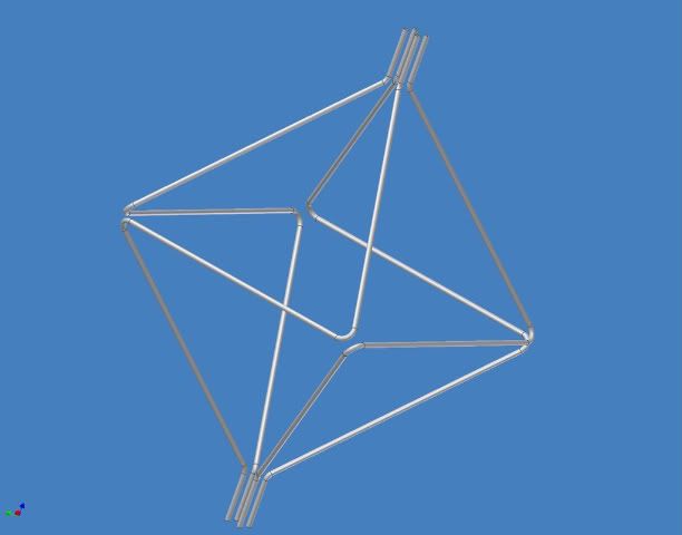
My theory on it is that the corners of the octahedron will close by the whiffleball effect sooner than the centers of the faces where the field is smaller.
A work-around could be to cross the leads somehow where they enter/leave the tetrahedron.
But that reduces the possibility of using the lead axis as electron/ion gun paths.
It also messes up the symmetry, but that might be what we need to do to tie a knot in the fields.
It also won’t work at the other 4 corners of the octahedron where the same problem exists (if we are talking about the same issue here.)
Another work around is to cross all the corners like a cyclone fence.
But this makes the fields very messy by adding a 3rd dimension to keep track of at each corner.
(I had this in my back pocket for another occasion but will lay it out now.)
Building the whole magrid like a cyclone fence could be used to create an arbitrarily large number of coils with the even number of faces at each corner.
This idea is totally half baked but might show some promise.
There are several obvious hurdles for it to jump, but that is for a different discussion.
Jmc,
By closing the holes of course I mean reducing them as much as possible.
I used the word “closed” to try to cut down the length of my already too wordy posts.
They get way too long if I try to qualify every statement.
Did I say “seal” if so I was being sloppy. Sorry.
Closed is a relative thing. This is the real world after all.
Further
My understanding of the loss mode in the original cusp machines (2coil) is that
there is a plane of zero field at the equator where the gyro radius goes to infinity.
I don’t see where we have zero fields in these devices (except within the conductive plasma.)
All points are surrounded by either a coil or a virtual coil.
Between tangent coils (also bends at triangle corners) the fields add and are concentrated so even higher.
Even if there were a zero field zone the gyro radius could be no larger than the spacing between opposite coils on a cube on or an octahedron. (this could be a reason to go to lots of small coils.)
So even then they can’t go very far before being pulled back in by the positively charged Magrid.
I don’t think we will have any true cusps. Not any more than one isolated coil has a cusp along its axis.
Does an isolated coil have a point cusp along its axis?
Then do 2 parallel wires have a line cusp along the plane halfway between them?
If so, then we have line cusps between the tangent coils.
But, that is where both the models and the experiments show the least leakage.
I think we are Shiny.
