Mutual Magnetic Repulsion Forces in the Magrid

Discuss the technical details of an "open source" community-driven design of a polywell reactor.

Moderators: tonybarry, MSimon

Post Reply
Aero
Posts: 1200
Joined: Mon Jun 30, 2008 4:36 am
Location: 92111

Mutual Magnetic Repulsion Forces in the Magrid

Post by Aero »

I posted this same topic in "General" but the thread was hijacked before anyone addressed the topic.

I have calculated the forces repelling opposite coils in the Magrid and came up with frighteningly large numbers. I used my best guess at WB-100 parameters and a formula from Wikipedia, here:

http://en.wikipedia.org/wiki/Magnet

Quoting the formula I used.
Force between two bar magnets

The force between two identical cylindrical bar magnets placed end to end is given by:[15]

F=\left[\frac {B_0^2 A^2 \left( L^2+R^2 \right)} {\pi\mu_0L^2}\right] \left[{\frac 1 {x^2}} + {\frac 1 {(x+2L)^2}} - {\frac 2 {(x+L)^2}} \right]

where

B0 is the magnetic flux density very close to each pole, in T,
A is the area of each pole, in m2,
L is the length of each magnet, in m,
R is the radius of each magnet, in m, and
x is the separation between the two magnets, in m

B_0 \,=\, \frac{\mu_0}{2}M relates the flux density at the pole to the magnetization of the magnet.

Note that all these formulations are based on the Gilbert's model, which is usable in relatively great distances. In other models, (e.g., Ampère's model) use a more complicated formulation that sometimes cannot be solved analytically. In these cases, numerical methods must be used.

Code: Select all

    Magnetic forces on the Magrid.                        
                            
Coil strength, B =        4    Tesla                
Magrid radius, r =        2    meters    Pole area, A = pi * r^2         12.56637061    m-square
single coil length, L =        0.4    meters                
Single Coil Radius, R =         2    meters                
Magnet seperation, x =        4    meters                
Permeability, Mu =        1.25664E-06                    

Force is calculated by formula,                             Force =

First Bracket F term =        16640000000                    
Second Bracket terms =        0.0625    0.043402778    -0.103305785    sum =    0.002596993    
                            
    F =     43213957.76    Newtons                
        4.32E+07    Newtons        1 newton =    0.101971621    kilogram-force
        4.41E+06     kilogram-force                
                            
Coil Length, pi() x d =        12.56637061    meters                
                            
    F_rate =     3.44E+06    Newtons/meter                
        3.51E+05    kg-force/meter                
My conclusion is that this force, 4.4 million kg-f, is so large as to need a closer look. It is a particularly important when superconducting magnets are considered. If I am not mistaken it is the superconducting wire that will be required to react this force so the wire will need to be strongly supported by structure. That will complicate the cooling problem and require nonmagnetic structure for support of the superconducting wire.

I would like to look at the repulsion forces for the whole Magrid, with contributions from the adjacent magnets, and perhaps even considering plasma pressures as well, but I fear that is a numerical calculation problem far beyond my poor abilities.
Aero

Aero
Posts: 1200
Joined: Mon Jun 30, 2008 4:36 am
Location: 92111

Post by Aero »

The equation used above to calculate force has a minimum for a magnet length of about 2.25 meters. (F = 28,803,322 Newtons.) I suspect this implies different magnetic field shapes for different shaped magnets. Magnets with conformal fields of course. Different field shapes could open or much better, close the cusps.
Aero

GIThruster
Posts: 4686
Joined: Tue May 25, 2010 8:17 pm

Post by GIThruster »

I haven't seen this posted in the Forum so:

http://www.mare.ee/indrek/ephi/
"Courage is not just a virtue, but the form of every virtue at the testing point." C. S. Lewis

Aero
Posts: 1200
Joined: Mon Jun 30, 2008 4:36 am
Location: 92111

Post by Aero »

I tried another formula and got better answers. I guess the question is, and always has been, "What is the right formula or mathematical technique for calculating the repulsive forces between the coils of the Magrid?"

For this formula I used a short, cylindrical magnet with thickness much less than radius, then I subtracted the thickness from the radius because the superconductor coil will be located on the circumference and no lines of flux will pass there. That left the magnet having an area circumscribed by the superconductor. With this formula, the smaller the superconductor cross-section, the smaller the repulsive force between Magrid coils. Some results:

Code: Select all

Using a different formula, Fx = (3*pi()/2Mu) * (B^2*R^4*t^2)/x^4)            
Coil thickness, t =        0.4    meters.
    Fx =     393660    newtons
        3.94E+05    
        4.01E+04    kg-f

Code: Select all

Using a different formula, Fx = (3*pi()/2Mu) * (B^2*R^4*t^2)/x^4)            
Coil thickness, t =        0.1    meters.
    Fx =     33888.2959    newtons
        3.39E+04    
        3.46E+03    kg-f
As you can see from the formula, the t^2 term dominates but the formula is also very sensitive to the coil radius. In fact, the idea of increasing the size of the Magrid may only have limited utility because repulsive forces go up strongly with radius. To me, the change in repulsive force from a change is the superconductor thickness implies a change in the shape of the magnetic field. Did Dr. Bussard or anyone look at the effect of magnetic field shape on polywell containment ability or does the wiffleball formation close the cusps equally, irrespectively of the shape of the coil magnetic fields?

What would be a good value to use for the thickness of the superconductor within the Magrid coils? And again, does this formula make any sense when applied to a vacuum core solenoid?

In case you are wondering how these forces could be very large, consider how a rail gun is made. A Magrid is like 3 single stage rail guns held in stasis.
Aero

93143
Posts: 1142
Joined: Fri Oct 19, 2007 7:51 pm

Post by 93143 »

Aero wrote:In fact, the idea of increasing the size of the Magrid may only have limited utility because repulsive forces go up strongly with radius.
Yeah, but they go down just as strongly with coil separation, which is through-zero linear with radius...
To me, the change in repulsive force from a change is the superconductor thickness implies a change in the shape of the magnetic field.
It's because the poles of your hypothetical cylindrical magnet are closer together. Lower dipole moment.

Subtracting t from R would also contribute...

WizWom
Posts: 371
Joined: Fri May 07, 2010 1:00 pm
Location: St Joseph, MO
Contact:

Post by WizWom »

Ceramics typically have a compressive strength in the hundreds of GigaPascals. Even your high estimate would allow supports with less than a thousandth of a square meter cross section, in pure compression.
Wandering Kernel of Happiness

Aero
Posts: 1200
Joined: Mon Jun 30, 2008 4:36 am
Location: 92111

Post by Aero »

Subtracting t from R would also contribute...
Yes it does. As for (R^4/x^4), I don't know why I didn't see that. But now that you point it out, I see that I need to add a term, dx, to account for additional separation of the superconductor coils due to the thickness of the cooling jacket. The ratio becomes (R-t/2)^4/(x+dx)^4. Here dx is the diameter of the cooling structure surrounding the superconductor, one radius on each side of the Magrid. With that, and for WB-100, I come up with:

Code: Select all

Using the formula, Fx = (3*pi()/2Mu) * (B^2*(R-t/2)^4*t^2)/(x+dx)^4)            
            
    Permeability, Mu =    1.25664E-06    
    Coil strength, B =    4    Tesla
    Magrid radius, R =    2    meters
    Coil thickness, t =    0.05    meters.
Magnet separation, x =        4    meters
    Structure thickness, dx =    0.4  meters   
            
    Fx =     6089.041766    newtons
        6.09E+03    
        6.21E+02    kg-f

If that is anything like reality then these forces are not so bad, not negligible but workable. I'm still not real confident that my equation reflects reality. I know it doesn't consider the torquing forces trying to flip the coils over. (Trying to align the coils N-S) Those forces should be zero if the coils are perfectly aligned and don't vibrate...

Edit: @ WizWom - My concern is with the distributed support needed for the somewhat fragile superconductor. Once that force is translated to an external ceramic support, yes, I'm sure you're right.
Aero

happyjack27
Posts: 1439
Joined: Wed Jul 14, 2010 5:27 pm

Post by happyjack27 »

Aero wrote:I know it doesn't consider the torquing forces trying to flip the coils over. (Trying to align the coils N-S) Those forces should be zero if the coils are perfectly aligned and don't vibrate...
i think the thing to do with that would be a sort of "perturbation analysis".
check what would happen if the alignment was off a little and then momentarily pushed with a force in line w/the magnetic torque ("perturbed"). then you see if the sum of the forces, including the momentary force, magnetic force, and the force of the physical structure pushing back against the torque, is positive or negative (relative to the magnetic torque).

by doing this you can find the "breaking points" ("unstable manifold") at various mechanical strengths, magnetic strengths, mis-alignments, and perturbations. maybe even make a graph. i wouldn't know all the equations for it but i believe that would be the way to go about it.

(edit) i should stress that the analysis; the sum of the forces, is working with <i>differentials</i> (dt).

Aero
Posts: 1200
Joined: Mon Jun 30, 2008 4:36 am
Location: 92111

Post by Aero »

happyjack27 wrote:
Aero wrote:I know it doesn't consider the torquing forces trying to flip the coils over. (Trying to align the coils N-S) Those forces should be zero if the coils are perfectly aligned and don't vibrate...
i think the thing to do with that would be a sort of "perturbation analysis".
check what would happen if the alignment was off a little and then momentarily pushed with a force in line w/the magnetic torque ("perturbed"). then you see if the sum of the forces, including the momentary force, magnetic force, and the force of the physical structure pushing back against the torque, is positive or negative (relative to the magnetic torque).

by doing this you can find the "breaking points" ("unstable manifold") at various mechanical strengths, magnetic strengths, mis-alignments, and perturbations. maybe even make a graph. i wouldn't know all the equations for it but i believe that would be the way to go about it.

(edit) i should stress that the analysis; the sum of the forces, is working with <i>differentials</i> (dt).
Since what little I've found on the Internet about it suggests that the torquing forces are not the same as the repulsion forces, I wouldn't know where to begin. I'll look some more but so far I've not found any equations or model that describe the torque except for one author saying that is is stronger than the repulsion force. What that means, I don't know.
Aero

Randy
Posts: 82
Joined: Mon Sep 20, 2010 5:40 am
Location: Texas

Post by Randy »

Hi Aero,

For calculating the magnetic forces between two coils I use an FEA program called FEMM. The FEMM program is free to the public and dirt simple to learn to use. I use it to calculate the forces on the rotors of magnetic bearings. After you have entered the geometry of the problem, the program will number-crunch a magnetic solution for you. From the solution page you can select an object and have the program perform a ‘force from Maxwell stress tensor’ calculation on that object. Sounds big and fancy but it’s just a mouse click and it calculates and displays the x and y components of the magnetic forces acting on that object.

I’ve used the output of the program to display pictures of magnetic field line shapes and magnetic flux densities on this forum before.

Again the FEMM program is free and very easy to use.

http://www.femm.info/wiki/HomePage

Hope this information is helpful to you.

~Randy

tombo
Posts: 334
Joined: Fri May 09, 2008 1:10 am
Location: Washington USA

Post by tombo »

This is an important number to nail down.
I got partway there with the numerical model I was building based on Kiteman's work.
But, new job has sucked up all time that might have gone into it for many months now. Sorry.

I think that this problem would be relatively easy to model ( at much lower currents.)

I propose:
Find or make a cubic cardboard box with one open side. (Scrounge at local liquor store or produce department)
Wind 6 identical coils maybe 12-24" diameter with as many turns as the builder has patience for. (transformer wire)
Place them on 5 of the box sides (duct tape and zip ties or twist ties etc.)
Place the 6th on another piece of cardboard in a vertical plane in the open box side.
Hang the 6th coil from thread (or the wires if they are fine enough) at 2 corners.
Wire in series (for identical currents) and apply current from a Variac or car battery and resistor or whatever is on hand. (I might try removing the heating tip from a soldering gun and connecting the coils there. It would have low voltage high current but maybe too high current for transformer wire. AC could be a problem.)
Install an ammeter.
Apply current and measure how far it swings away from the stator (ie the 5 fixed coils).
Apply a little trigonometry and out pops a measured force data point.

I estimate that a handy hardware hacker with the right stuff on hand and enough space to work could do it in a weekend.
That is certainly less time and effort than goes into the computer models.
I think everyone would feel better with even one data point to calibrate the computer models.

The model could get more sophisticated force vector sensors, different coil sizes, different currents, etc. for more data points, if you were so inspired.
Paper doll models are a venerable engineering tradition.
-Tom Boydston-
"If we knew what we were doing, it wouldn’t be called research, would it?" ~Albert Einstein

vernes
Posts: 135
Joined: Tue May 13, 2008 10:22 am
Location: The Netherlands

Post by vernes »

GIThruster wrote:I haven't seen this posted in the Forum so:
http://www.mare.ee/indrek/ephi/
11 matches on ephi

TallDave
Posts: 3152
Joined: Wed Jul 25, 2007 7:12 pm
Contact:

Post by TallDave »

This discussion makes me wish we had video of WB-6 flying apart. Or did it just short out and sit there smoking? I've never seen a post-mortem pic.

Thanks Randy, that's very interesting.
n*kBolt*Te = B**2/(2*mu0) and B^.25 loss scaling? Or not so much? Hopefully we'll know soon...

Nik
Posts: 181
Joined: Thu Mar 12, 2009 8:14 pm
Location: UK

Failure modes...

Post by Nik »

Surely, you'll need some sort of triangulated space-frame to absorb forces from asymmetric fields ??

A bit like fly-wheels, there's a LOT of potential energy in the system...

KitemanSA
Posts: 6180
Joined: Sun Sep 28, 2008 3:05 pm
Location: OlyPen WA

Re: Failure modes...

Post by KitemanSA »

Nik wrote:Surely, you'll need some sort of triangulated space-frame to absorb forces from asymmetric fields ??

A bit like fly-wheels, there's a LOT of potential energy in the system...
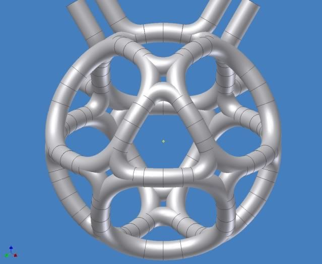
I've always considered the bowed MPG with X-Cusps (this)
Image
image by tombo
to be the best way to take the mag-forces, and all the other potential issues like that (Navy HI shock for instance).

PS: Not to put too fine a point on it, but flywheels store a lot of kinetic energy and very little potential. The MaGrid is more like a tightly wound spring or pressurized flask, no?

PPS: tombo's work here is marvelous!

Post Reply