KitemanSA wrote:Randy wrote: Is this an issue?
Good question. At the present only the MPGs have had this plan-form. I have read that they were amongst the only other machines to do fusion, so perhaps the condition is of LESS importance in this design than in a round plan-form machine like WB6.
Personally, I like the bow-legged real-real version of this design. This one!
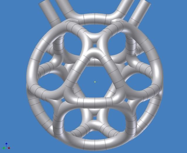
Kudos to tombo! marvelous graphic!
Yes – yes, I see what you’re saying: “Why not make the virtual poles (about the triangular faces) real coils as well?” ‘tombo’ does indeed make good 3-D graphics!
As I mentioned earlier my concern about the B-field through the triangular faces of the cuboctahedron being almost double that through the square faces. I thought that this phenomenon might introduce more inductance into the electric circuit of the magnet coils.
Coil inductance is a big issue with prototype magrid configurations because they will almost always be of the pulsed current type (large capacitor-bank discharge test platforms).
This led me to favor the octahedron (eight-coil) configuration. But I did a quick double-check analysis and discovered that even though the B-field through the triangular surfaces is almost double that through the square faces, this does not affect the overall inductance of the electric circuit. My reasoning follows:
Total coil flux linkage (flux) = B * Area.
L(inductance) = Nturns * total coil flux linkage (flux) / i.
My previous analysis shows that for the triangular faces the B-field magnitude increases in the same proportion as the decrease in the area of the triangles as compared to the total surface area of the cuboctahedron. Thus causing no net change in the [Total coil flux linkage (flux) = B * Area] through the triangular faces. Therefore the L(inductance) of the circuit is not affected by this phenomena.
This observation shows that (as far as electric circuit inductance is concerned) the six coil cuboctahedron square plan-form magrid configuration is likely a better design than an eight coil triangular plan-form octahedron configuration because it only features six coils, thus introducing less overall coil circuit inductance.
Kiteman, I definitely see why you like the bow-legged real-real design.
The KISS (Keep It Simple Stupid) paradigm has never failed me. So for simple prototype designs I believe the “squared” cuboctahedral design is the most desirable configuration to work with. It can’t be much more difficult to fabricate six square plan-form coil spools than six round plan-form coil spools. i.e., the six coil cuboctahedron square plan-form magrid configuration. As posted by you earlier:

…This is likely the best simple magrid configuration for prototype construction.
~Randy