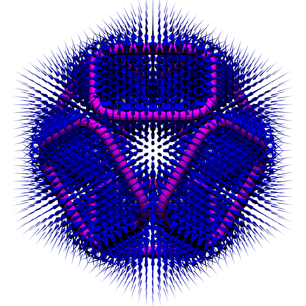
Now that I have the model working here is some data analysis:
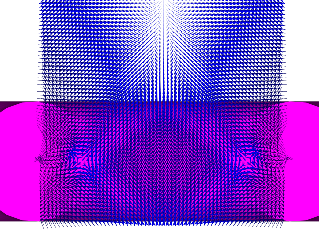
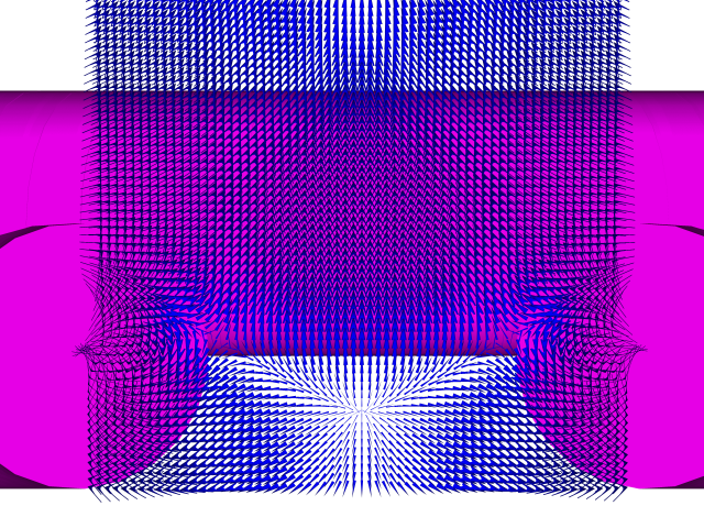
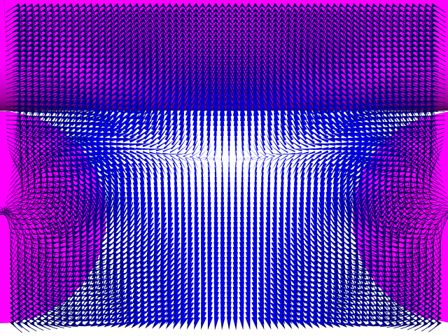
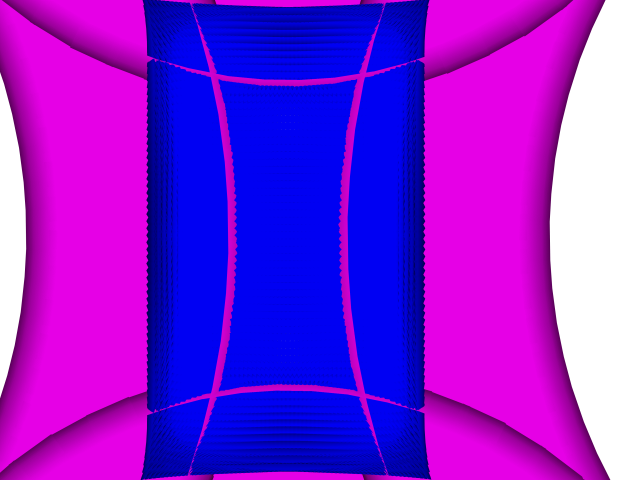
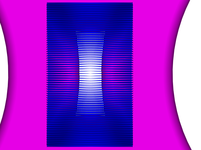
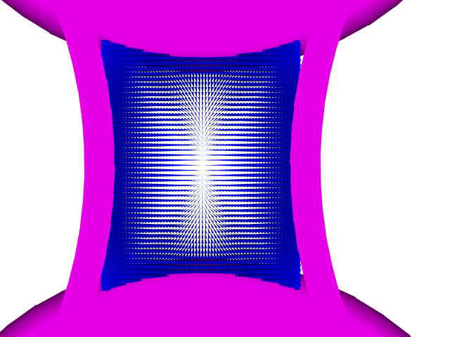
Slice thru the middles of the 2 short sides
Showing field nulls and weakening field as it gets further from (above) the nulls.
http://i299.photobucket.com/albums/mm31 ... 000_-6.png
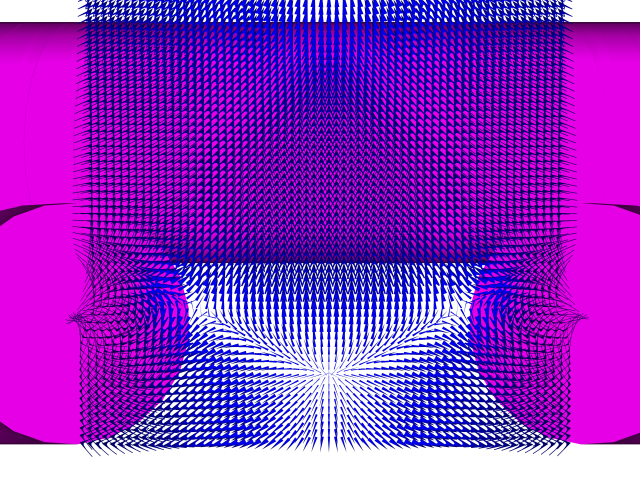
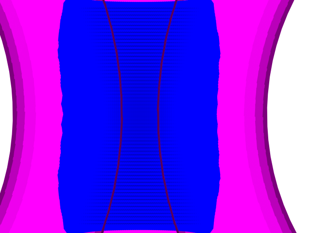
Same with different rendering parameters
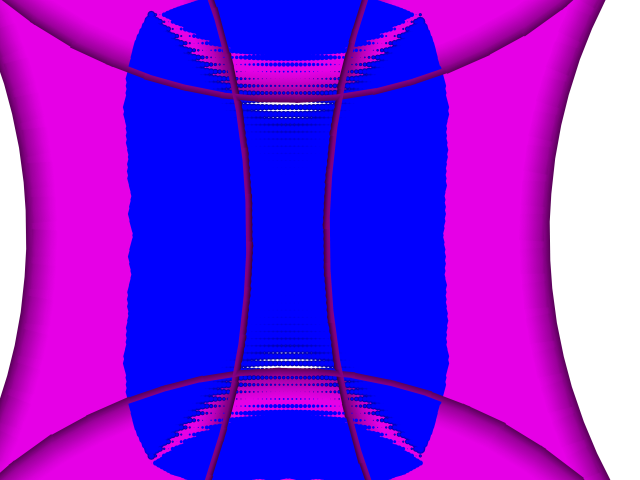
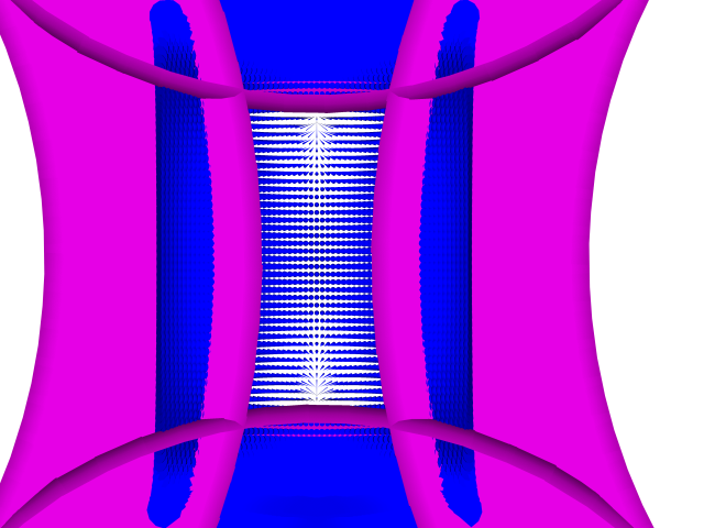
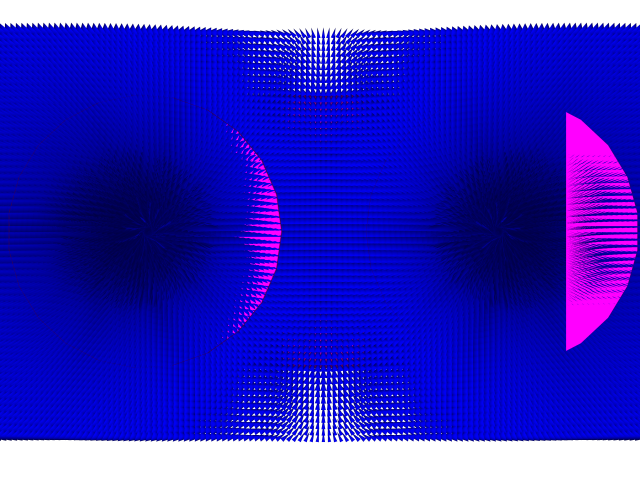
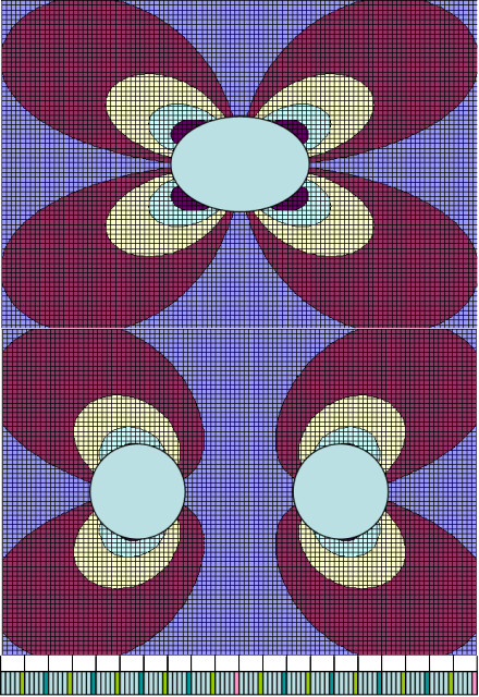
Slice in the plane of the coils looking from the top. (i.e. from the outside looking toward the center of the Polywell.)
Showing crescent shaped field nulls.
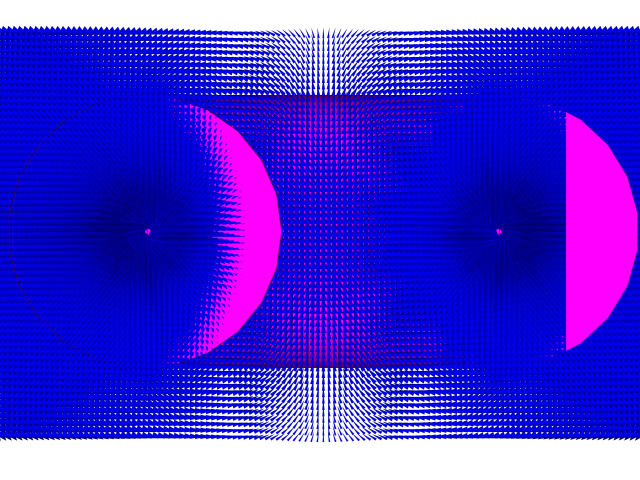
Slice 1 cm above the plane of the coils.
Showing crescent shaped field nulls smaller.
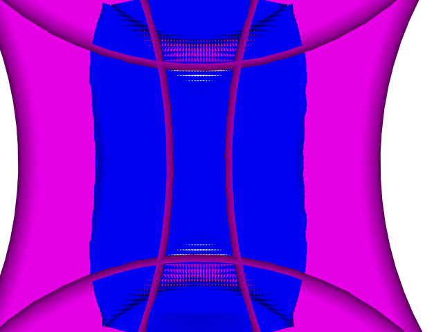
Slice 2 cm above the plane of the coils.
Showing crescent shaped field nulls smaller still.
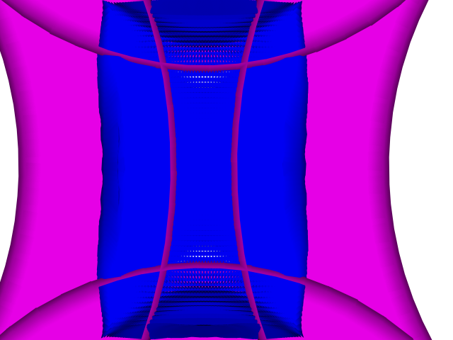
Slice 3 cm above the plane of the coils. Showing crescent shaped field nulls pretty much gone.
http://i299.photobucket.com/albums/mm31 ... 000_-2.png
Slice 5 cm above the plane of the coils.
Showing the crescent shaped field nulls gone.
http://i299.photobucket.com/albums/mm31 ... 000_-1.png
Slice 20 cm above the plane of the coils.
Showing weakening fields as we get further from the coils.
http://i299.photobucket.com/albums/mm31 ... 00_Top.png
oooooooooooooooooooooooooooooooooooooooooooo
The coils really have a 3D geometry and the shorter legs will be further from the poly well center point.
This difference can be controlled by adjusting the relative coil curve radii.
I hypothesized a few weeks ago that the field nulls may be reduced or eliminated by offsetting one set of crossovers. So…
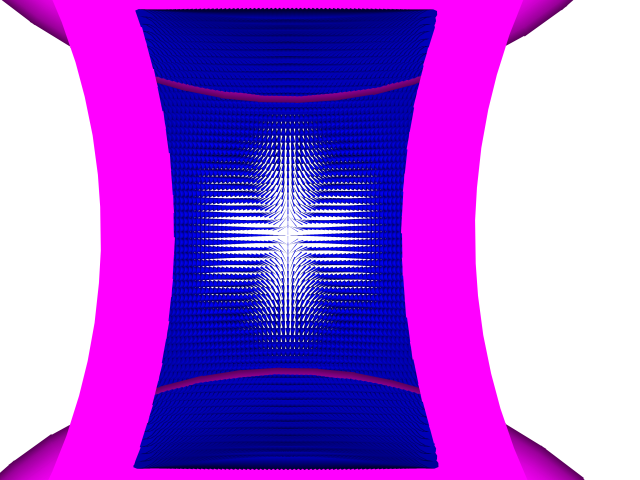
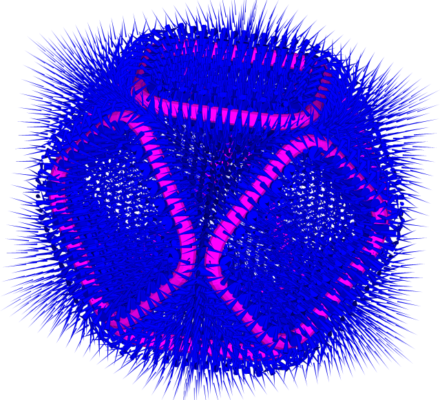
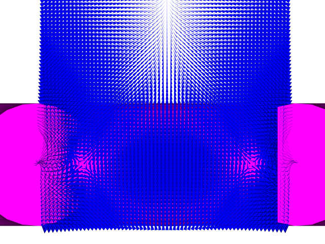
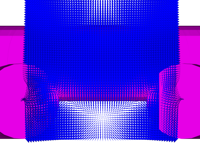
Slice thru the middles of the 2 short sides with:
Coils offset by 10 cm
Showing weakened crescent field nulls at +1 cm and new field null at -4 cm
The new null is where the field enters from 2 opposite directions and leaves in the 2 orthogonal directions which is the same geometry as the crescent ones.
Notice also how the field above this interesting region is much stronger than when the coils were aligned.
This should provide a barrier between the reactor core and the weakened fields.
Same with different rendering parameters
http://i299.photobucket.com/albums/mm31 ... 10_Rig.png
Slice +1 cm above the plane of the coils looking from the top. (i.e. from the outside looking toward the center of the polywell.)
Showing the field nulls no longer crescent shaped and with arms reaching out toward the new null.
Slice -4 cm above (i.e. below) the plane of the coils.
Showing the new field null from the top.
oooooooooooooooooooooooooooooooooooooooooooo
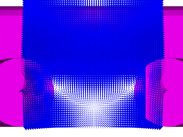
Slice thru the middles of the 2 short sides
Coils offset by 15 cm
Showing weakened field nulls at +1 cm and new field null at -4 cm
Notice also how the field above this interesting region is even stronger than when the coils were offset by 10 cm.
Same with different rendering parameters
http://i299.photobucket.com/albums/mm31 ... 15_Rig.png
Slice +1 cm above the plane of the coils looking from the top. (i.e. from the outside looking toward the center of the polywell.)
Showing the field nulls no longer crescent shaped and with arms reaching out further toward the new null.
http://i299.photobucket.com/albums/mm31 ... 015_-1.png
Slice -4 cm above (i.e. below) the plane of the coils.
Showing the new field null in the center looking from the top.
http://i299.photobucket.com/albums/mm31 ... 15_Top.png
oooooooooooooooooooooooooooooooooooooooooooo
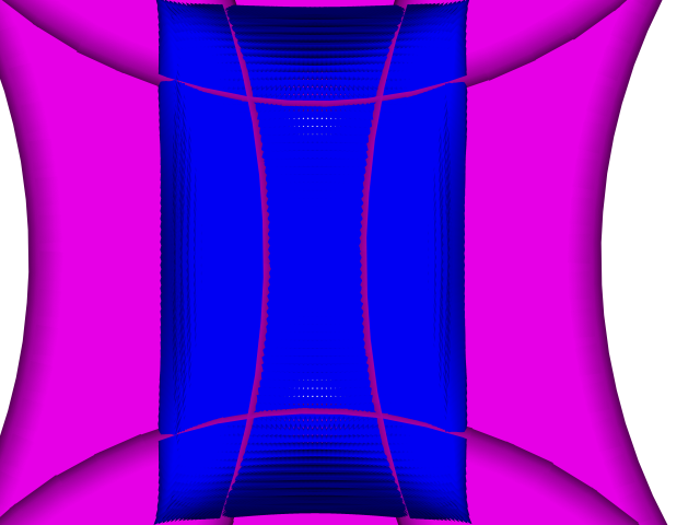
Slice thru the middles of the 2 short sides
Coils offset by 20 cm
Showing crescent field nulls merged into one field null at +5.6 cm and strong even fields above about 10 cm.
In fact the fields are strongest just above the null shielding it from electrons.
Same with different rendering parameters
http://i299.photobucket.com/albums/mm31 ... 20_Rig.png
Slice +5.6 cm above the plane of the coils looking from the top. (i.e. from the outside looking toward the center of the polywell.)
Showing the merged field null in the center looking from the top.
http://i299.photobucket.com/albums/mm31 ... 020_-1.png
Slice +20 cm above the plane of the coils.
Showing even strong fields between the reactor core and the region of weakened fields.
http://i299.photobucket.com/albums/mm31 ... 20_Top.png
Offsetting the closer pair of cross connects toward the reactor core will shield the field null from the escaping electron flux (& ion flux too of course). The more offset the better for this effect. Less offset helps other parameters of course.
The changes with coil offsets are so big that we really have to do this over (heavy sigh) with the real 3D positions of the coils.
This flat approximation really is not good enough to show some major field features because the positions change much more than the offsets that I just modeled.
I predict an enhanced strong field region just inside (toward the reactor core) the region we are exploring here. (This would be a good thing.)
If you send me the list of the x,y,z point positions for the 3D coil locations, I will work on it some more. (It needn’t be the same length list as before.)
The AutoCAD drawing, showing all these configurations as different layers, is available on request but beware it is 147 Megabytes big.
My little old computer complains about its size but can barely handle it.
If you can view it you can glean much more information about the details of the field vector behavior.
I could make the rest of the tools available if you want but they are not set up for others to use.
--Edited for multiple errors and insights---
(Sorry, but sometimes I have to actually see the final product and think about it for a while, then I see more stuff. Somehow it is easier to see errors after I let it go.)