no the theoretical sphere centered on the center of the device passing through all the coils. ie. the sphere defined by the coils. The vacuum chamber is neither here nor there at this point.Sphere = vacuum chamber shell?
No. Outward from the center of the machine.By "outward" do you mean tending to open up the "v"s?
That is exactly what I was trying to point out.If so, I think I disagree. There may be the attempt by one magnet to open it up, but the magnet next to it is pushing the other way on each of the segments. Net cross beam load, nil. There WILL be a load pointing radially outward from the center of the MaGrid.
What is your design? I would like to see a picture, even if it is just a scan of a sketch.Those are taken up easily by my design.
They will be inside a coolant channel that should isolate it from the bending forces. In any case it must bend enough to coil or it is useless for our purposes.But the SC wire probably won't take that kind of strain. Anything more than ~0.2% and you start losing capacity fast. Some toughened wires go to 0.4%!
The multiple parallel sc wires will need to be loose enough in the channel to slide past each other as the outer layers are bent. The ends are free so they can move. This will also allow them to adjust their positions independently during operation without stressing themselves.
Possible but a lot of work especially if the rectangular cross sections don't want to line up across the various regions.How bout the "union" idea? Anyway, for a first try, can you just make the pipes rectangular cross section, 1" radial for each 4" transverse, and the duplicate it 3 times at the appropriate extended radius? This would result in the square cross setion SC core that folk are bandying about.
The corners are going to look like a highway interchange.
plasma are the only ones that RE-circulate.or electrons in the plasma?
RightActually, it makes for quad REAL magnets and NO nubbins (nubbins being defined as those little cross pipes in the middle of the funny cusps that carry little or no current and just get in the way!)
That though true is not what I meant. Look at the details. You have one pass at, say, 2 m radius then another at 2.1 m radius then another at 2.2 and another at 2.3 . The field line wrap around each of them, and they are parallel therefore there will be field nulls between each pair of them.True. He anticipated it, they're called "funny" cusps and he didn't seem to care. He just made a mistake by putting the nubbins in the middle of them.
Also what is the field in the little square hole?
Please answer this, it will help me understand.Do you mean to have the whole thing in 1 casing or do you envision 4 separate casings?
Are you trying for something like this: http://www.justodians.org/SphericalMagn ... agPic1.htm
viewtopic.php?p=11900&highlight=#11900
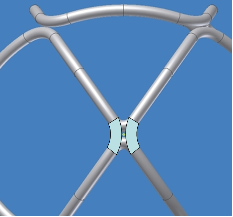 This shows the intent of what the final arrangement would be, magnets all around the funny cusp. Strength members inside the pipe and carrying all the radial load in membrane stress, the most efficient kind of structure. I believe the magnets may need to be moved back some more, but I can’t be sure until it is analyzed.
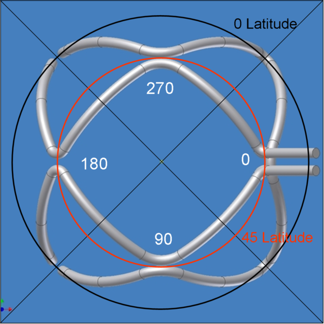 This shows your north polar view (great!) with some labels. If you look at all the “corners” on the black circle (the equator), you will see that half are curved toward the squares and half toward the triangles. The same can be said for all the other latitudes except at 45 degrees latitude and 0 longitude where the pattern is broken. Indeed, the MPG could be split there and have two pairs of I/Os which would keep the plumbing simple but would shorten the coolant run by half. It would also make the item completely symmetrical and assure that when the 4 strata are overlaid, each corner has two and exactly two strata running thru it. This will assure a significant degree of magnetic protection for the corneres which are the “cross-connects”.


