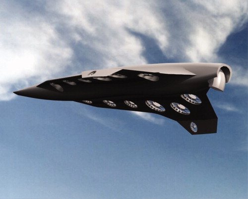
rjaypeters wrote:DeltaV suggested cascading hubless thrusters of different diameters on the same duct to use at different air speeds. An interesting idea, efficient from a packaging perspective; the problem is the duct losses for any given active thruster would be increased by the the drag of thruster blades which are not actively being spun.
That's not exactly what I wrote, rjay. Here's what I wrote:
DeltaV wrote:For the air turbine, with several stages inline, imagine each stage's rpm controlled independently to optimize overall thrust/efficiency at any flight condition.
Says nothing about any of the fans being stopped, or different diameters.
A gradual variation in duct diameter over the fan section might be appropriate, but CFD sims and experiments would have to determine that. This is
not the compressor/combustor/turbine arrangement of a conventional jet engine, where large variations in diameter along the axis are necessary due to large changes in flow characteristics. The axial change would be much more gradual here since the Brayton cycle is not involved. Variable intakes and exhaust nozzles for the non-fan portions of the duct might be appropriate, depending on the operational envelope and vehicle design.
I'm envisioning several electric, counter-rotating stages per duct, closely spaced, each stage's rpm controlled independently. Non-rotating segments with variable stator vanes (common for conventional jet engine compressors) might be interspersed where appropriate, depending on CFD results. Keeping the stages closely spaced limits the turbulence seen by downstream stages and maximizes counter-rotation efficiency benefits.
Varying the blade angles for the spinning segments is possible, but I wouldn't add that complexity unless there was a good reason to do so. Now, if the rotors had variable blade angles, you
could stop one and use it as a variable stator segment. Lot's of interesting possibilties when you go all-electric.
Conventional jet engines have two or three spools, giving two or three simultaneous rpms for the various sections. Generally, tailoring the rpm of each bladed segment to the local flow improves efficiency and performance. Pratt and Whitney's latest is the Geared TurboFan, which separates fan speed from spool speed through a gearbox.
Each stage of an electric ducted fan can have its own rpm, optimized for the conditions at that stage's position along the axis. Said fan conditions varying much less radically than for a Brayton cycle engine's compressor/turbine sections, of course.
Reverse thrust via electrically reversing the rotor spin directions is also a possibility. Say your vehicle has several, parallel, multistage, electric ducted fans for forward flight. For VTOL, you might be able to use some of those for rear lift and some (running in reverse) for forward lift, with variable-geometry devices to direct the flows. Admittedly, a non-trivial integration challenge, but not that different from what F-35B already does.
This would free up space otherwise taken by dedicated lift fans/doors and maybe reduce lift system weight:
(Edit: fixed dead link, again)

vs.

