So its been a bit quiet over here in the design forum. While the rest of the world argues over non Maxwellian distributions and core synchronization issues, i think there is still a lot that can be gained from designing a virtual polywell. One that does not need expensive components, one that simply tantalizes and excites the mind on paper.
I have been thinking about the e guns a lot lately. Building designing and synchronizing 6 E guns is a lot of work, possibly just as much as the magrid.
In one of the papers Dr. Bussard considered briefly magnetron's vs E guns for the electron source. After repairing C band weather radars in an avionics shop, i would have to champion magnetrons for their power, efficiency, reliability and pulsed/CW performance.
So can anyone here think of some fundamental reasons not to use Magnetrons ? I have a L-3 unit in my hand right now capable of 6kw@ 9345mhz. If i had a working set of Polyhedral coils and a vacuum tank (been rubbing every lamp i find lately) is there any reason why i couldnt start forming a virtual cathode tomorrow ?
Magnetrons vs E guns
Magnetrons vs E guns
Purity is Power
A magnetron is an e-gun - it just has chambers on it make the microwaves. If you have a background gas and enough field strength to ionize, then you get electrons from the excitation process. What is the efficiency at the pressure you need to run the device at?
I like the idea of a virtual device. The trick is to pick a good model. If we use several different models for collisional interactions and they all give similar results, it's a good bet reality will be similar. If they all give totally different results, it might gives us some ideas for really simple experiments to perform to determine which model is more realistic.
I'm building virtual coils right now. Unfortunatly, I can't see them yet - but I'm working on that too! Too bad I have to eat and sleep...
Let me reliterate a little.
One needs an electron source to form a virtual cathode.
How will injecting electrons at 1mhz, 10mhz, 100mhz, 1ghz effect the formation of a virtual cathode if any?
Do the guns really need to be time aligned / in phase for a virtual cathode to form ?
How long would it take to inject x amount of electrons from x guns to form a suitable potential well ?
These are important questions. I really think only few people are really switched on to how a true polywell will work.
Purity is Power
I'm guessing the electrons only need to show up within the whiffle ball & then to turn on the power. I recall a relation 'tween electrons/size of device/required # of ions, to make neutrons.Keegan wrote:
Do the guns really need to be time aligned / in phase for a virtual cathode to form ?
I like the p-B11 resonance peak at 50 KV acceleration. In2 years we'll know.
Lets look at the physicality of the situation.
At 300 Mhz the wavelength is 1 m. No help.
If we go with microwave oven magnetrons we are at roughly 3 GHz. That is a 100 cm wave length still too large for a WB-6/7. It would definitely require phasing. Not so easy to do with magnetrons separated by a few feet.
C band gets up to about 6 GHz. Now we are at 50 cm. A little better. My guess is we have to go up to at least 30 GHz.
You still have the problem of coupling and reflections. We are firing into a closed metal container with a bunch of metal objects in the center.
And when we are done what do we have? Thermalized particles. Fine for tokamaks. Not so hot for Polywell. I think electron guns are a better deal. You can buy them off the shelf with vacuum cut off valves so you can change filaments without destroying the machine vacuum.
Unfortunately smaller machines require bigger electron guns because of losses.
Bigger is better.
Dr. B is talking about 50 to 100A electron sources for a full size machine (don't recall if that is total or per gun). That is rather heavy. Even if it is total.
Update 8 oct 007 Jeez did I screw that one up. 300 MHz is 100 cm wavelength. 3 GHz is 10 cm. Revise in you head accordingly.
Last edited by MSimon on Mon Oct 08, 2007 9:53 am, edited 1 time in total.
Answers
MSimon microwave ovens operate 2.45ghz. That equates to a wavelength of 12.24cm. Most design and calculations use the 1/4 wavelength as the fundamental unit.
I have been writing a paper lately about my polwell. Be it a collection of fresh ideas and perspectives that i hope will influence the machine's final design. The topic of electron injection is, i believe critical to polywell's success so i have chosen to publish one now and hopefully stir up some debate.
So how does one inject high energy electrons at tunable frequencies, in phase, into the core of the polywell, efficiently as possible ?
With a ring resonator.
The drawing is just a concept not to scale. The concept has been proven to work over a range of frequencies, powers and dimensions. As we gather more information about the polywell we will soon see whether or not it can be applied.
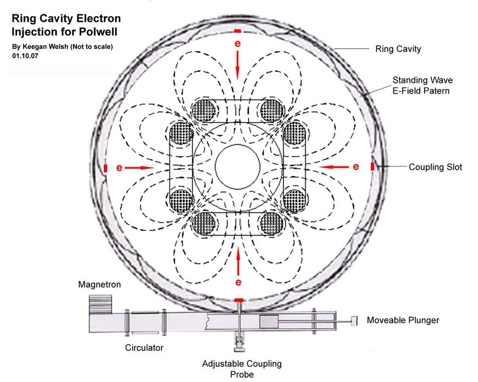
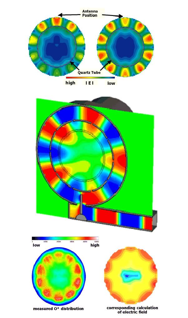
Plasma processing is enjoying some innovative technology as the industry matures. One of them is the SLAN, an abreviation for SLotted ANular waveguide. Microwaves are generated in the magnetron, sent through a circulator connected to a dummy load to protect the magetron from reflected power. A coupling probe sends the energy into a ring resonator where it forms a standing E field. Microwaves are ejected from the coupling slots into the vacuum chamber. The device is tunable and the adjustable coupling antenna and plunger adjust the reflected power and can vary the phase +/- 15 degrees.
for more information
http://www.nanomaster.com/NM/Brochures/SLAN.pdf
http://www.cst.com/Content/Applications ... icleId=124
I have been writing a paper lately about my polwell. Be it a collection of fresh ideas and perspectives that i hope will influence the machine's final design. The topic of electron injection is, i believe critical to polywell's success so i have chosen to publish one now and hopefully stir up some debate.
So how does one inject high energy electrons at tunable frequencies, in phase, into the core of the polywell, efficiently as possible ?
With a ring resonator.
The drawing is just a concept not to scale. The concept has been proven to work over a range of frequencies, powers and dimensions. As we gather more information about the polywell we will soon see whether or not it can be applied.
Plasma processing is enjoying some innovative technology as the industry matures. One of them is the SLAN, an abreviation for SLotted ANular waveguide. Microwaves are generated in the magnetron, sent through a circulator connected to a dummy load to protect the magetron from reflected power. A coupling probe sends the energy into a ring resonator where it forms a standing E field. Microwaves are ejected from the coupling slots into the vacuum chamber. The device is tunable and the adjustable coupling antenna and plunger adjust the reflected power and can vary the phase +/- 15 degrees.
for more information
http://www.nanomaster.com/NM/Brochures/SLAN.pdf
http://www.cst.com/Content/Applications ... icleId=124
Purity is Power
Yes. I'm aware of microwave frequencies. I was just trying to give ROM numbers. Do it in your head type stuff.
Typically 1/10th wavelength or less is the area of low interaction with structures. The 1/4 wave distance is the dividing line. At 1/30th the wavelength edge diffraction becomes insignificant.
Lets look at some numbers.
3 GHz = 10 cm 1/4 wave = 2.5 cm = 1 inch.
30 GHz = 1cm 1/4 wave = 2.5 mm = 1/10th inch
For a 1 m structure for minimum interaction the wave length should be 1/30 th of a meter. That is 3 cm so 10 GHz Magnetrons ought to be fine. With oven magnetrons barely acceptable. You still have the phasing problem if you use more than one unless the gas is highly absorptive at the microwave freq. It is possible that the magnetrons will self synchronize from reflected power. My RF experience peters out at 100 MHz so I would defer to some one with more expertise. I could have this all screwed up.
In any case microwaves add to the energy dispersion of the beams. Not a problem in tokamaks. Definitely a problem in IEC.
Magnetrons do not lend themselves to fine modulation, electron guns do. This is very important if you need a special injection profile to "neutralize" the colliding beams.
So I would favor electron guns in an experimental reactor for reasons of versatility. Once we know what kind of profiles work other methods of generation could be worked out.
Keegan,
I worked on some early computers with edge rates of 1 nS. (cira 1967 - TTL).
To keep the cabinets (typical rack mount jobs) synchronized the cables had to be cut to within 1" of each other. This was for 30 ft cables. On the order of a full size Polywell reqmt. No problem in '67 with RG-58 type cables. If we need to do better than that - small dia. hardline. I worked on FM stations in '62 that used 3 1/8" hardline and a diplexer to phase combine two 25 KW RF power amplifiers. However it is a tad unwieldy. Shouldn't be necessary as grid modulation power should be low. In fact it has to be low or you burn up the grids.
Another alternative is teflon cable of about RG-8 size. It is capable of 5KW @ 50 ohms which means a peak working voltage of about 700 V. That should be adequate. I estimate grid voltages more on the order of 100 V. So plenty of margin.
Another possibility is copper stripline or microstrip on mylar. Mylar is good for about 7,000 V / .001" - working voltage 1/2 that. As long as the power is low so there is not much heating that might work out.
In any case I can't wait for WB-7 results to come out so we are given some real parameters to design with.
Nothing wrong with speculation though just to keep the brain cells warmed up.
I love doing this open source. To mangle Howl - I saw the best minds of my generation...
Could you be a little more specific ?MSimon wrote:In any case microwaves add to the energy dispersion of the beams. Not a problem in tokamaks. Definitely a problem in IEC.
One thing i was banking on was the direct energy conversion system being a massive positively charged grid surrounding the outer perimeter of the machine. Wouldnt any stray electrons/reflections be absorbed by this ?
Purity is Power
Yep stray ions will be absorbed by the grids or walls. Stray electrons by the walls. Provided they are at high enough energy to be a problem.
That adds to the losses. Not a good idea.
You want to keep everything as mono-energetic as possible.
I'm not saying it wouldn't work. It very well might. We just don't know enough yet to a priori design it.
To get to the required level of knowledge I think modulated electron beams are the way to go for flexibility.
Don't let anything I say here stop your thinking. It might just be the fix we need if other approaches don't pan out.
If the maGrid absorbs ions this can work to an advantage. The ions would be positively charged and so would the maGrid surface. So ion absorption could become a way of keeping the the maGrid positively charged.MSimon wrote:Yep stray ions will be absorbed by the grids or walls. Stray electrons by the walls. Provided they are at high enough energy to be a problem.
That adds to the losses. Not a good idea.
Should this idea have a thread in the theory section?
The problem is that the grids will be at 50 KV or 200 KV (depending on design. Given a +5 ion charge that means 250 KeV or 1,000 KeV relative to the ions. Given 2.5 MeV ions the remainder is losses. That requires cooling for the net difference.MisterX wrote:If the maGrid absorbs ions this can work to an advantage. The ions would be positively charged and so would the maGrid surface. So ion absorption could become a way of keeping the the maGrid positively charged.MSimon wrote:Yep stray ions will be absorbed by the grids or walls. Stray electrons by the walls. Provided they are at high enough energy to be a problem.
That adds to the losses. Not a good idea.
Should this idea have a thread in the theory section?
This is kind of a theory/design problem so I think it is OK here.
A POPS engine ?
Agreed. We are going to need some very flexible electron beams, to probe and excite the hidden resonances in the machine. Anyone familiar with the radio art know that you can have either power or flexibility. Looks like i just found both.MSimon wrote:To get to the required level of knowledge I think modulated electron beams are the way to go for flexibility.
http://eurekaaerospace.com/hpems.php
Although its seems early in development and an order of magnitude higher in frequency than current POPS estimates, it looks like they have created an extremely powerful and flexible electron source. Should prove very useful in a research reactor. 100J is a fair kick and they are only using a spark gap (imagine what you could do with IGBT). I would love to study their output topology. I want one (for use with or without a polywell!)
Purity is Power