Page 10 of 11
Posted: Tue Feb 23, 2010 8:20 pm
by KitemanSA
Folks,
As I see it, the serpentine coils and the independant coils would need the same number of nubs, i.e., one "set" at each location that the coils approach. I SUSPECT the same is true of porcupine quills, but I am not sure.
The only configuration that eliminates the large number of nubs or quills is the X_cusp unit and that can be made either with independant coils or with serpentine coils. So in reality, the real distinction between the two is how easy it is to cool, and that remains to be seen.
I reiterate that I like the X_MPG because it eliminates the nubs and quills and provides a minimal I/O set to interfere with electrons outside the MaGrid.
Just an opinion. It might not work out as I envision!

Posted: Tue Feb 23, 2010 8:20 pm
by MSimon
KitemanSA wrote:MSimon wrote:Kiteman,
I will reiterate. If I understand you correctly the fields are pointing the wrong way.
Then I suspect you don't understand me correctly.
Given tombo's graphic I provided several posts ago, the X_MPG, do you think those fields are going the wrong direction? If so, we have an interesting discussion ahead.
As I understand it we have a slinky in a tube. The field will be axial to the tube (mainly).
Posted: Tue Feb 23, 2010 8:26 pm
by MSimon
tombo wrote:MSimon wrote:All standoffs should have full current so they are magnetically shielded.
It is not just Amps that count. It is Amp - Turns.
Yes, of course.
To be more precise, the standoffs should have enough current to create a high enough B field at their surfaces to magnetically shield them from the (hopefully somewhat shadowed) plasma environment they live in.
This is hard if the coil has many more turns than the standoff.
It is impossible if there is no current in the standoff. (This was my point.)
If the standoff diameter can be reduced significantly by reduced heat load from residing in a shielded area and by having a reduced SC cross section, then it will have less reduction in surface B field (and in magnetic shielding) compared to the main coils themselves.
Advantage-One pass serpentine coils.
The fields desired require 1E7 Amp Turns (2 m dia coils). The SC wires can carry 100 Amps.
Do the math. It is not favorable.
Posted: Tue Feb 23, 2010 9:07 pm
by KitemanSA
MSimon wrote:KitemanSA wrote:MSimon wrote:I will reiterate. If I understand you correctly the fields are pointing the wrong way.
Then I suspect you don't understand me correctly.
Given tombo's graphic I provided several posts ago, the X_MPG, do you think those fields are going the wrong direction? If so, we have an interesting discussion ahead.
As I understand it we have a slinky in a tube. The field will be axial to the tube (mainly).
As I said, you don't understand it. We have SC TAPE in a tube. The slinky diameter is the diameter of the WHOLE MaGrid, making it easy to wrap the core. In the "tube" is a large number of turns of tape oriented like the rings of Saturn (edge on to the center).
In the ASCII graphic I presented earlier, the row of vertical pipes (|) represents the cross section of one one side of the slinky.
Assume for a second that I am NOT an idiot and that my design will in fact work. Figure out how to make it so. THEN you will understand me!

Posted: Tue Feb 23, 2010 9:34 pm
by Aero
As I understand you, your really running the tape exactly as you would run copper wire. The benefit of the superconducting slinky tape conformation is that it is pre-formed to conform to the Magrid curvature and so less risk of damage to the superconducting tape as you lay it up. After all, one crack in the superconductor would really mess things up.
Posted: Tue Feb 23, 2010 9:43 pm
by mvanwink5
KitemanSA,
After thinking about the continuous SC winding, one pass per coil, through the nub to the next coil, etc, until all coils get one pass, then repeat until the turns required are met, I think it would be doable. Also the nubs would get full complement of turns. I can't see how the coolant plumbing works yet. Also, I don't understand the purpose of the triangular coils as they would have to have opposite B field to the square coils. Wouldn't their B field be stronger than the square coils due to smaller size? Wouldn't strong triangular coil fields make it more difficult for the wiffle ball to close off?
If issues all worked out I can see merits...
Posted: Tue Feb 23, 2010 11:55 pm
by mvanwink5
KitemanSA,
Ok, I can see how the plumbing could work, but someone else will have to run the flows, pressure drop and heat loading. Also rather than require a slinky twist to the SC wire, it would seem that the SC bundle could be made with a slight roll in the coils. That could be verified by testing it out on a mock up. I still have doubts about the triangular coils, but the magrid could be done without them and you could reduce the nubs by half. I also can see how the magrid could be constructed in a shop, perhaps by a large motor repair shop. Most are capable of forming their own motor coils, though working with SC tape would be unusual for most! Thanks for sticking with your idea.

Posted: Wed Feb 24, 2010 12:25 am
by KitemanSA
Aero wrote:As I understand you, your really running the tape exactly as you would run copper wire. The benefit of the superconducting slinky tape conformation is that it is pre-formed to conform to the Magrid curvature and so less risk of damage to the superconducting tape as you lay it up. After all, one crack in the superconductor would really mess things up.
Precisely, except the tape stands tall around the MaGrid rather than flat. This allows it to bend tightly at the corners of the polygons.
Posted: Wed Feb 24, 2010 12:47 am
by KitemanSA
mvanwink5 wrote:KitemanSA,
Ok, I can see how the plumbing could work, but someone else will have to run the flows, pressure drop and heat loading.
For the cuboctahedron (C-O), tombo's great graphic, the cross-section (minus thermal protection system) may be something like this. Of course, this is intended to be tubular copper rather than SC tape, but the concept can be similar. Just mentally replace the square tube with verically oriented tape.
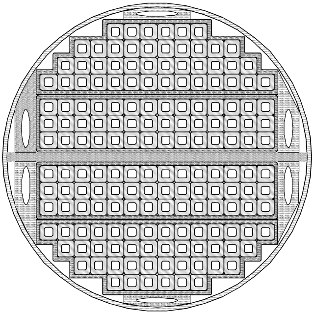
There are 4 separate bundles (strata) of tubes (tapes) all encased by separate casings. My prior ASCII graphic has the same set-up except the bundles are rectangular and to X-section is square.
If you do the C-O serpentine layout like this, the four separate strata can then be rotated around the "north pole", the second out rotates 90, the third out rotates 180 and the outermost 270. That will return them all into alignmnet over all the MaGrid EXCEPT that the places where the "nubs" would be are replaced with X_Cusps like in tombo's graphic. If properly wrapped, each side of the X-Cusps will have two and exactly two strata running thru each of the 4 sides rather than the 4 running thru everything else. But my prelim calcs suggest that should be sufficient.
I am not convinced that the Icosidodec MPG can be wound to balance an X-Cusp so would probably need nubs.
Posted: Wed Feb 24, 2010 12:52 am
by Betruger
Kiteman you can probably sketch what you're thinking of fairly easily by using a free and simple modeling app like Google Sketchup, then upload pics of the design to a free host like flickr, photobucket, or imageshack.
Posted: Wed Feb 24, 2010 1:01 am
by KitemanSA
What is it that you need a sketch of?
Posted: Wed Feb 24, 2010 1:05 am
by Betruger
Just a suggestion.. The ASCII sketch seems to be an obstacle to communicating that design.
Posted: Wed Feb 24, 2010 2:24 am
by KitemanSA
Does this help?
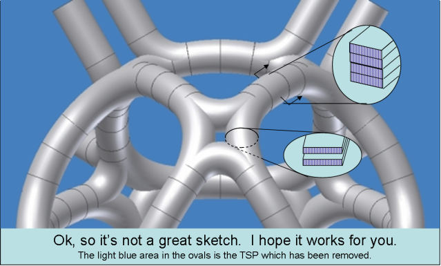
The vertical dark blue lines are the tapes standing on edge inside four independant casings (strata). NO, this is not an engineered design, just a basic concept. The "3D lines" should actually be slightly curved, down for the 4 stack and sideways for the two stack. But I think you should get the idea.
Posted: Wed Feb 24, 2010 2:45 am
by Betruger
I get it, just saying so for anyone else who didn't yet.
Posted: Mon Mar 01, 2010 3:17 am
by tombo
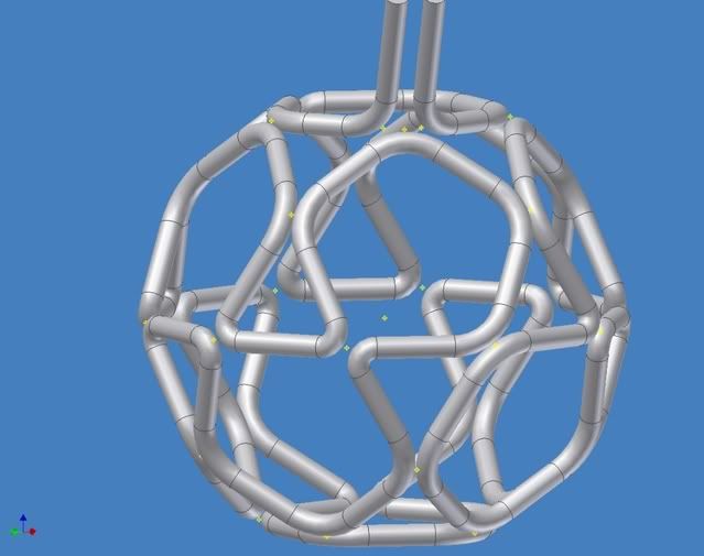
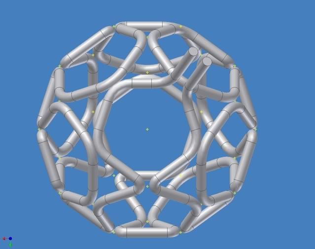
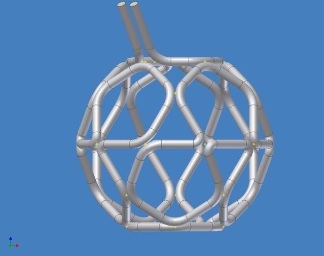
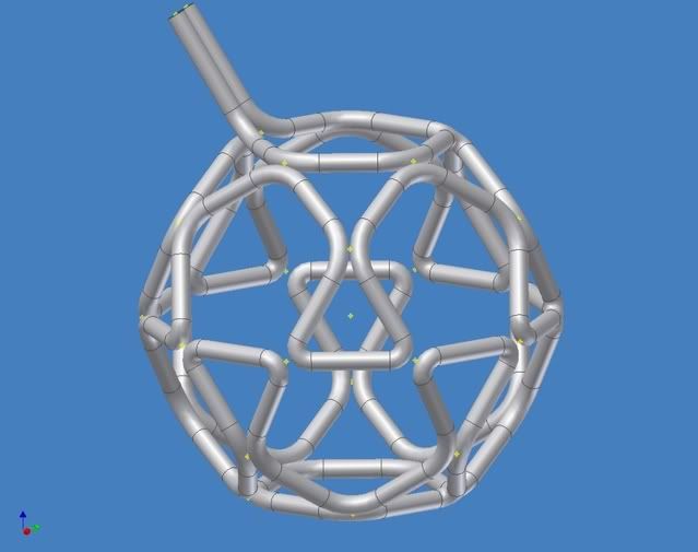
WOW!!!
That was a mind bending experience!!!
3 meter dia magrid
8" thick "coils"
More views of this?
Note that 60 deg bends are too sharp for normal piping practice but if larger they cause really big gaps between the adjacent bends.
The small yellow targets are at the vertices of the icosidodecahedron.
I had to pause my following of all conversations here to get this done.
Famous Last Words:
It should not be too bad.