Virtual Polywell
I vote for free (as in speech) open source Polywell simulation, not some expensive proprietary software. I can't help with programming itself (I know C, but I am not that good in math involved in simulations), but maybe I can help with other things - source code repository (Bazaar, Mercurial, Git or Subversion), help with BOINC (if it will be used in future), etc.
Nope, I have not looked at it. And I couldn't afford it any way.
Besides, I want to do a full 3D sim because the polywell is not 2D symmetric. And it's more fun
My electron_fluid.c failed:
So I am definitly going to start over. I think abandoning gsl for a crude <value at a point> * <delta volume element> is a much better way to go. If it is fast enough, I can go back to using lots of points and the integral should be close enough.
I also got a chance to read one of the POPS papers. They assume spherical symmetry and do 1D calculations in that paper (it's from 2005). If we can do 3D I think it will help the fusion community a lot. And we can have a lot of fun too!
Besides, I want to do a full 3D sim because the polywell is not 2D symmetric. And it's more fun
My electron_fluid.c failed:
Code: Select all
gsl: qag.c:248: ERROR: roundoff error prevents tolerance from being achieved
Default GSL error handler invoked.
Aborted
I also got a chance to read one of the POPS papers. They assume spherical symmetry and do 1D calculations in that paper (it's from 2005). If we can do 3D I think it will help the fusion community a lot. And we can have a lot of fun too!
So is that different or the same as Bussard's 1/(r^2) assumption about the electron distribution? 1/(r^2) is spherically symmetrical.drmike wrote:I also got a chance to read one of the POPS papers. They assume spherical symmetry and do 1D calculations in that paper (it's from 2005). If we can do 3D I think it will help the fusion community a lot. And we can have a lot of fun too!
More like "on failure". I'm re-writing electron_fluid.c completely so that I attack the problem from a different direction. Instead of using the gsl integration routines, I will sum over the points I have and just multiply by the density and volume element divided by the distance between every point to the place in question.
It's an interesting geometry problem. As Indrek pointed out, there is 48 fold symmetry. So I can take every point in 1/48 volume and use that density with 48 different distances. The trick happens on symmetry planes where the fold maps back onto itself. There are some planes of 24 points, and some lines of only 8 points. I have to account for these special cases, and try to do it in an efficient way. I am certain that many eyes will determine much better ways than what I find, but I want to try hard to be efficient from the start.
To answer the question about Bussard's assumption and the POPS assumption, yes, there seems to be a large difference. However, if you look inside the MaGrid there is a relatively large zone where both assumptions are similar. I take the density to be
1/(eps(-a*r^2) + b*r^2)
For r^2 small, the b*r^2 term is << the exponential term and the density is "flat". So there is a region where the POPS assumption is valid.
The other interesting thing about the POPS paper is the amplitude of the RF they apply to the grids. It is very small - on the order of 10 volts. Compare that the 10 kV I was playing with! The key difference is that they are moving ions and I was moving electrons. So it could be that the proper combination of a low voltage, low frequency RF with a medium voltage high frequency RF will maintain stability and create continuous pulsed motion for power.
The main problem I have with the physics assumption I've made is that everything starts Maxwellian. I'm not sure that's a good idea. But it makes the math a whole lot simpler. That is something to explore over various experiments.
If the Q is high the RF power need not be large.
From what I could tell of the POPS experiments the Q seemed low - on the order of 2 to 10 (SWAG). But that is a SWAG based on relaxation times for frequencies on the order of 10 to 20% away from the resonance. It would be nice to have more detailed data.
It may be that the Q is dependent on ion/electron losses and if the losses are low the Q will be much higher (duh).
I have been trying to get some of the fusor kids to do the experiment. No luck so far.
One thing that might work is to feed the DC through a parallel resonant ckt tuned to the POPS freq so the tube becomes its own RF generator. All properly phased nice and neat like. No external drive required at all. A Q of about 20 to 100 should work nicely. Big honking coils made of silverplated Cu tube and capacitors with air or Teflon dielectric.
Did some one say Tesla Coil?
http://www.teslasystems.com/
*
Engineering is the art of making what you want from what you can get at a profit.
I like that idea a lot! There's a million volt Tesla coil here in Madison that the physics prof's use to show off to the kids at "The Wonders of Physics" Very impressive! Be a great toy on a fusor too 
In the mean time I'm still debugging a new attack. Not quite an infinite loop, but it's going way too slow. I think I figured out I'm computing the same distances every time through the loop, and I can speed things up 100 times with a lookup table. DOH! One step at a time....
Now if I can just figure out a way to get a Jacob's Ladder in the mix, we'll have a true mad scientist lab going!
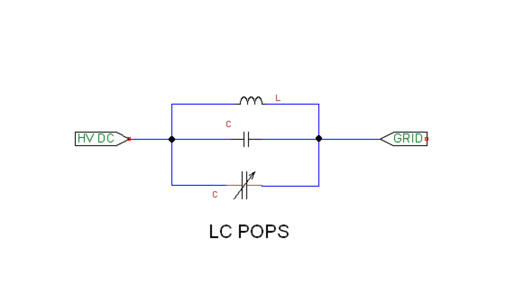
I wrote it up in more detail with a little better schematic and some useful math at:
http://iecfusiontech.blogspot.com/2008/02/lc-pops.html
If the coils are made close to self resonance then a very small capacitor can be used to resonate the coil. That means the unit could be tuned over a small range by putting a sheet of dielectric between the capacitor plates.
The first thing to do is to get your fusor operating properly and then use a spectrum analyzer or 100KHz to 30 MHz radio receiver to find out what the natural frequency is.
A high frequency capacitive voltage divider with a diode detector hooked to the HV between the LC and the grid would be a good idea for tuning the coil. Tune for maximum RF.
The HV side could be from .5 to 2 pF (depending on frequency). With the low side capacitance on the order of 50 to 200pF (dependent on the high side capacitance). What you want is 100:1 divide ratio. Roughly. To start. If you use a 1N4148 diode as a detector. You should be able to go from about 100 VAC to 3000 VAC (diode limit is 3750 VAC - actually 1/2 of 75 PIV guaranteed*100). If the voltages you get are outside that range adjust your divider accordingly.
A lot is going to depend on lead dress. Keep everything as short as possible.
Engineering is the art of making what you want from what you can get at a profit.
You know that is just the way I felt about it.dch24 wrote:So you're telling me every fusion power station will need, absolutely need, a Tesla coil somewhere near the fusion core?MSimon wrote:Big honking coils made of silverplated Cu tube and capacitors with air or Teflon dielectric.
Did some one say Tesla Coil?
Is this Christmas in February? :D
What I'm thinking is that we have a Q multiplier here. If we use Q multiplication to raise the RF at the grid that should enhance the production of RF further raising the RF drive.
It will be interesting to see if it has any effect on fusion output. And what it does to losses.
Any way there is something like a 10% or 20 % chance we will do it this way. If it works you could control the feedback by adjusting the tuning.
Another way to tune it to start would be to use a fluorescent tube in the vicinity and tune for maximum brightness. That should be good enough to start.
Really the deeper we get into this the more it looks like a gadget from a movie set.
Engineering is the art of making what you want from what you can get at a profit.
Let me add one minor word of caution. We may not use this on the initial test devices until we are sure of the stability and frequency of POPS. For testing it would be more useful to have a power amplifier driven system with octave band output filters.
I have put a bit up at fusor.net about this and it seems there is an interested party. If he gets results I might change my attitude.
A while back some folks were fantasizing about how to use a Tesla coil to run a fusion machine. It looks like it might be the other way around.
I remember it was that guy with the AIDS cure and an underwater Tesla coil IIRC. He may have stumbled on to something.
Engineering is the art of making what you want from what you can get at a profit.
I've posted a new version of electron_fluid.c which is not yet fully debugged, but should be close. At least it will give everyone some new ways to think about the problem of how plasmas interact with themselves.
The idea is to build tables of what amount to constants for the purposes of the integration. The only thing different in every term of the sum is the distance between points. But this version groups all values containing the same electron density so that only a single multiply is needed for that part and the distance from the point in question to the symmetry points is all that is computed.
With 100 radial steps, there are 101*102*103/6 = 176,851 points of symmetry. Each one of those has to be summed by the distance to the other 48 (usually, there are some points with a lot fewer symmetry points). So the total number of loops is ~48*176851^2 =~ 1.5e12 calculations. That it only takes a few hours on a 4 year old desktop computer says alot about the computing power available!
I may cut the number of radial steps by 2 so I only have 50 radial steps. That reduced the problem by 2^6, which is significant. And it should still give enough accuracy to tell something useful.
Certainly to tell me what size of Tesla coil to build
I have been adding to :
http://iecfusiontech.blogspot.com/2008/02/lc-pops.html
Including some cheap RF detectors.
http://iecfusiontech.blogspot.com/2008/02/lc-pops.html
Including some cheap RF detectors.
Engineering is the art of making what you want from what you can get at a profit.
Very nice Simon! Hardware seems so much simpler than the software I've been trying to do. I'm lost in book keeping - it looks like I can't count right. I've found a few dumb bugs with wrong indexes (k's where I should have j's kind of thing), but I think I need to think some more about how I count over the points in the volume that affect each other.
darn details!!
darn details!!
Yeah. Except that idea has been sitting there for 30 years and no one else saw it. I have to admit that without reading the MIT papers this last year I wouldn't have seen it either.Hardware seems
It reminds of of when Dr. B was talking about cusp losses and said it took him 11 years to see the obvious. And a lot of people used that against him. Forgetting that a lot of people besides Dr. B looked at it and didn't see the obvious either.
How about Indrek's 48 way slice of the reaction volume. Brilliant bit of work. What makes it really brilliant is that it is obvious in hindsight.
For all you young 'uns out there forgive me for the next bit: I believe this project is in the main old man's work. Because it is only when you have enough experience do you see the possible connections between seemingly unrelated ideas. Not only that - people under 50 have had very little exposure to vacuum tubes. They lack a certain fingerspitzengefühl for the work. I mean - who studies klystrons any more?
What I think we have here is an ion klystron rather than an electron klystron.
http://en.wikipedia.org/wiki/Klystron
What is so slick is that instead of having to use an external power source the reactor acts as its own RF generator. That is what I call economy of force. If it works.
Engineering is the art of making what you want from what you can get at a profit.