DrMike,
Well, like I said it was half baked.
Now that you point it out I see 2 null field points just outside the small overlapping region rather than one inside it. I was only seeing the space inside it.
There are other concerns too but that one is a show stopper.
Do you think Tom Cuddihy’s concerns about the octahedron are show stoppers?
(I’m afraid I’m still not seeing it.)
Cusps:
Then, I think any coil will be surrounded by cusps where its range of influence stops and another’s begins.
The octahedral family then has tricuspid “Y” shaped cusps in the center of each triangular coil and line cusps leading from one of its branches to the second coil over, or to the feed lines.
But if they are ok in the corners and edges of a truncube I hope they will be ok in an octahedron.
magrid configuration brainstorming
Aren't the cusps in the Bussard machine different in that the fields do go to zero because of the opposing fields? Or maybe I have to recalibrate. :-)drmike wrote:The easiest way for me to think about coils and fields is to draw circles around the wires. Just like an electric circuit needs a complete loop to work, and magnetic field needs a complete loop to exist.
If you make a "cyclone fence" with wires, the magnetic fields will cancel in the small hole between the connecting wires. That's way too big a leak.
Cusps are not "zero", they are places where "circles" from other points on a wire (or different wires) meet. So they are regions of high field pointing in a specific direction. The center of a coil is cusp because the circles from opposite ends of the coil meet. The line between coils is a cusp as is the corner. In all those places, the field points in one direction, and it is definitely not zero.
Engineering is the art of making what you want from what you can get at a profit.
I keep reading that the magnetic field inside a PW is null at some points, and I cant see why.MSimon wrote:Aren't the cusps in the Bussard machine different in that the fields do go to zero because of the opposing fields? Or maybe I have to recalibrate.
I've done some calcs and (in absence of plasma) the only point where they indicate that the B-field is 0 is at the geometric center of the cube.
They say that the field maximize at the points of [almost] contact of every two coils, and that at each corner B is at least 3 times stronger than at a coil's center.
Further more, all the B gradients are outbound at EVERY INTERIOR POINT of the truncated cube (B diminish from the coils to the center).
Are my numbers wrong?
Last edited by charliem on Fri Jun 13, 2008 5:09 am, edited 1 time in total.
Get your iron filings out and face two like poles towards each other. Tap the card with the filings and look for places that the filings do not move much when tapped. Now think of that in 3D. The same is true at the cusps. The place where the fields meet has zero field. Increasing rapidly from that point.charliem wrote:I keep reading that the magnetic field inside a PW is null at some points, and I cant see why.MSimon wrote:Aren't the cusps in the Bussard machine different in that the fields do go to zero because of the opposing fields? Or maybe I have to recalibrate. :-)
I've dont some calcs and (in absence of plasma) the only point where they indicate that the B-field is 0 is at the geometric center of the cube.
They say that the field maximize at the points of [almost] contact of every two coils, and that at each corner B is at least 3 times stronger than at a coil's center.
Further more, all the B gradients are outbound at EVERY INTERIOR POINT of the truncated cube (B diminish from the coils to the center).
Are my numbers wrong?
Engineering is the art of making what you want from what you can get at a profit.
Simon, sorry but I think that this time you are wrong.MSimon wrote:Get your iron filings out and face two like poles towards each other. Tap the card with the filings and look for places that the filings do not move much when tapped. Now think of that in 3D. The same is true at the cusps. The place where the fields meet has zero field. Increasing rapidly from that point.
Your argument is valid for the magrid center, but not for its corners.
To make the experiment more alike the configuration of a Polywell the two magnets should not be opposed, but put in a way that their N-S axis are at 90º. You'll find then that their respectives fields dont nullify each other.
Field-lines are a good aid when thinking about magnetic fields, but you have to be careful because they dont always reflect the field form or magnitude accurately. When things get too complicated to imagine I prefer maths.
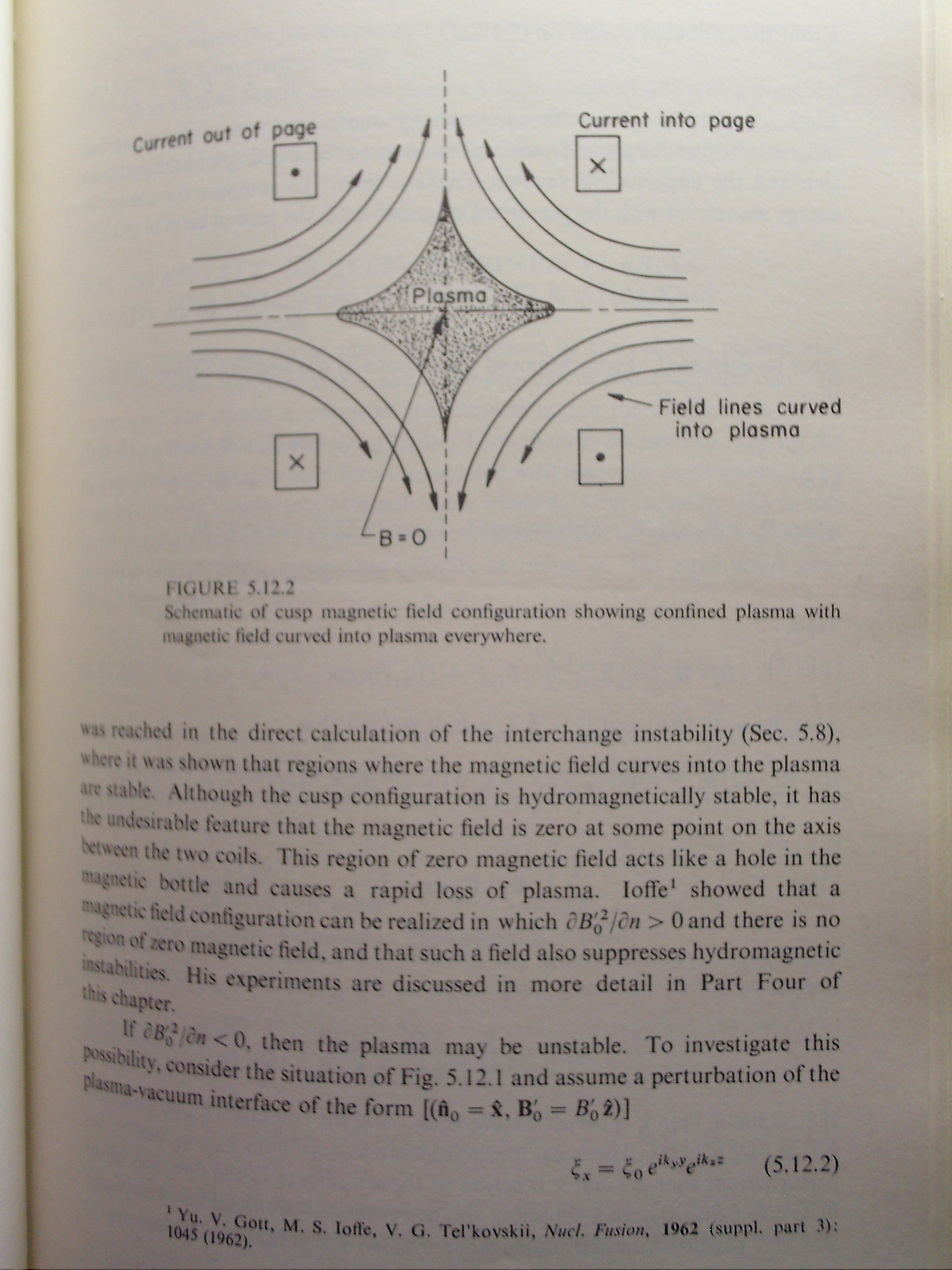
This is why I like the "right hand rule". You put your thumb along the current and your fingers show the direction of B. charliem is describing the field correctly, and if you look at this picture you will see the difference between the center of coil cusp and in between coil cusps.
The whole section describes how this kind of B field creates a stable plasma form.
The whole section describes how this kind of B field creates a stable plasma form.
I don't see why they would go to zero. I mean, in the cusp there's no field but that's just because the fields don't fit together perfectly, not due to any cancelling effect.MSimon wrote: Aren't the cusps in the Bussard machine different in that the fields do go to zero because of the opposing fields? Or maybe I have to recalibrate.
That's my understanding, anyway.
From the Valencia paper:
http://www.askmar.com/ConferenceNotes/2 ... 0Paper.pdf
Initially, when the electron density is small, internal B field
trapping is by simple “mirror reflection“ and interior
electron lifetimes are increased by a factor Gmr, proportional
linearly to the maximum value of the cusp axial B field.
This trapping factor is generally found to be in the range of
10-60 for most practical configurations. However, if the
magnetic field can be “inflated“ by increasing the electron
density (by further injection current), then the thus-inflated
magnetic “bubble“ will trap electrons by “cusp confinement“
in which the cusp axis flow area is set by the electron gyro
radius in the maximum central axis B field. Thus, cusp
confinement scales as B2. The degree of inflation is
measured by the electron “beta“ which is the ratio of the
electron kinetic energy density to the local magnetic energy
density, thus beta = 8(pi)nE/B2. Figure 16 shows two
means of reaching WB beta = one conditions.
The highest value that can be reached by electron density is
when this ratio equals unity; further density increases simply
“blow out“ the escape hole in each cusp. And, low values of
this parameter prevent the attainment of cusp confinement,
leaving only Gmr, mirror trapping. When beta = unity is
achieved, it is possible to greatly increase trapped electron
density by modest increase in B field strength, for given
current drive. At this condition, the electrons inside the
quasi-sphere “see“ small exit holes on the B cusp axes,
whose size is 1.5-2 times their gyro radius at that energy and
field strength. Thus they will bounce back and forth within
the sphere, until such a —hole“ is encountered on some
bounce. This is like a ball bearing bouncing around within a
perforated spherical shell, similar to the toy called the
“Wiffle Ball“. Thus, this has been called Wiffle Ball (WB)
confinement, with a trapping factor Gwb (ratio of electron
lifetime with trapping to that with no trapping).
Analyses show that this factor can readily reach values of
many tens of thousands, thus provides the best means of
achieving high electron densities inside the machine relative
to those outside the magnetic coils, with minimal injection
current drive.
Dave there IS a b-field in the cusps of a Polywells, and a quite strong one.TallDave wrote:I don't see why they would go to zero. I mean, in the cusp there's no field but that's just because the fields don't fit together perfectly, not due to any cancelling effect.
What defines a cusp is not the absence of magnetic field, but that its vector (B) is parallel to the speed vector (v) of the expected particles, in that case the cross product (v x B) is cero so the force over a moving charge is null even if B is not (again, as long and only if it moves in the same direction that B aims to (or its exact opposite)).
http://en.wikipedia.org/wiki/Lorentz_force
Baseball Polywell
I still think you could make a polywell with a single coil - shaped like the stitching of a baseball.
I think you are right and, besides that, the field gets stronger near the coil's interior faces also.TallDave wrote:So when we say the cusps are "closing" as beta approaches unity, what we're really saying is that the angles are becoming more favorable to confinement.
Seedload. An interesting shape, I'll give it some thought.
Oh Crap!!
I figured out why my plots don't look right. The theory I wrote up is wrong! Talk about back to the drawing board. I think this is an interesting excercise, so I'll keep plugging at it until I get it right.
At least I'm pretty sure the code I wrote is doing what I expect - that took long enough to get right. But the field lines it produced are simply wrong, and looking at the math I can see why.
DOH!
OK, I fixed it. Here's a rough plot of half the coil (I must have a bug some where, but I don't have time to find it just now....)

I fixed the theory and the code. In that same directory is the plotting routine I used.
A good visualization tool would allow moving the data so a better idea of how it really looks can be more easily grasped. I can see the null spots are near coil structure, and that would cause problems. An interesting idea to play with though.