Ok, thanks for the patience jmc, I think I'm finally catching on. The big idea is that the B-field is pretty much zero in the center of the machine, where as in a mirror it may be small, but non-zero. And then the electron loss isn't about the mirror ratio, but the gyro-radius like you said.
@tombo: I read in one of Dr. Bussard's reports (look on askmar.com) that the electrons are supposed to create counter-currents opposing the magnetic field; that's what produces the 'superconducting balloon.' And that should act like an extra set of coils ... hmm, I think Indrek posted a field snapshot of a magrid with two coils, that should approximate this effect. It makes sense, because if the magnetic field is putting pressure on the electron plasma (the whole "beta" concept in confinement), you expect the electron plasma to be putting out an opposing field.
Looking from that perspective, the electron plasma really just superimposes it's own field over the field from the coils, so that the resulting field for the whiffleball is just kind of the sum of the two fields. So no, it' doesn't push the magrid field tangentially, but the result is that there's a spherical surface of sorts, and the field lines are tangent to it on most of the surface, and perpendicular only over small areas (the cusps).
So Tombo, I guess I'd go with your #2 option there.
JMC, DrMike etc feel free to correct me if I'm wrong, I'm just kinda talking this out.
magrid configuration brainstorming
Best simple one paragraph explanation I have seen so far.Looking from that perspective, the electron plasma really just superimposes it's own field over the field from the coils, so that the resulting field for the whiffleball is just kind of the sum of the two fields. So no, it' doesn't push the magrid field tangentially, but the result is that there's a spherical surface of sorts, and the field lines are tangent to it on most of the surface, and perpendicular only over small areas (the cusps).
My latest theory is that the big deal with the Wiffle Ball is not closing the holes but in getting the electrons in circulation patterns that avoid the holes. i.e that circulation dominates vs the counter emf changing the magnetic fields. Although it seems that shaping up the fields has got to help too by narrowing the loss cones. Add in that the loss cones are not really total loss cones and could probably be improved with focusing grids and you have a low loss system.
Engineering is the art of making what you want from what you can get at a profit.
Thank you! I imagine I've oversimplified it somehow though.
WB machines have huge recirculating electron currents, millions of amps IIRC. So it makes sense that directing those electron currents could help control losses.
What if a tetrahedron magrid was made? Here's my thoughts: it would have 4 corner cusps and 4 coils w/ center cusps versus 8 corners and 6 coils for a truncube. So fewer coils to build, and fewer cusps. Also, I was wondering whether the transparency to alpha's might be better?
Yeah, I see what you mean! Good luck writing that code. I remembered seeing that Indrek had a solid-angle calculator for a magrid, but it only did the truncube shape.
hmm, another crazy idea here: this document says on page 6 that the loss thru a point cusp at the end of a mirror machine is only "a few percent" of the loss through the line cusp. So how about using a few more coils to make a set of point cusps out of that line cusp? Or another way to think of it, using a WB-like contraption as an 'end-cap' for a mirror tube. Or like stretching a WB machine out. (That paper talks about using rf plugging of the cusp against ion loss, but it could easily be done fore electrons.)
Let's see: I'm guessing that it probably wouldn't be worth it b/c the mirror part would introduce the possibility of instabilities and transports and all that. It might also cause trapping of the alphas which would spoil direct conversion. Then again, this setup might be good for DD fusion, since the mirror coils at least would be outside the machine. The cusp-producing coils at each end would have to be at ground potential, so the electrons would have to be injected at high energy, so that's back to operating like PXL or HEPS: no recirulation, so cusp losses are energy confinement losses. But the advantage here is that the mirror segment offers extra confinement volume/area without adding more cusps, so maybe the electron loss rate won't be killer.
Yes, that looks good.electron plasma really just superimposes it's own field over the field from the coils,
But, I’m still not sure how the plasma ball assumes a spherical shape without peaks at the coil centers & corners.
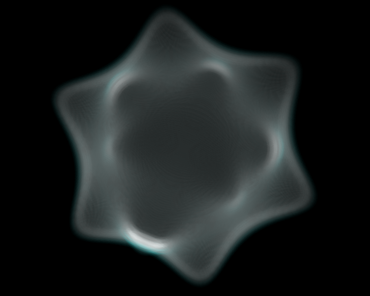
Here is Indrek’s model of the core. (probably before inflation begins)
http://www.pld.ttu.ee/~indrek/ephi/chimera6.png There is a better view of it somewhere.
Look at it at low pressure then watch it inflate.
At the coil centers the B pressure is lower so the plasma will bulge out.
As it inflates the peak will be less & less but it won’t to go away.
Do we have a way to make it go away?
Maybe it goes far enough away?
Does the plasma sphere have a “surface tension”?
Good idea.
Here is Indrek's post to "electron recirculation" Fri May 16, 2008. 8:48 pm (I tried to quote it, but I can’t point to it any more efficiently than this.)
The point where those opposing fields come together in the center is very sharp.
This is a good thing.
Another subject:
I can see the line cusps (although I’m not seeing their coils) in the configuration of the machine in the RF plugging document. (p.22)
Would someone please draw the line of the line cusp on the truncube?
I just can’t visualize it.
-Tom Boydston-
"If we knew what we were doing, it wouldn’t be called research, would it?" ~Albert Einstein
"If we knew what we were doing, it wouldn’t be called research, would it?" ~Albert Einstein
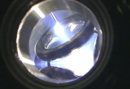
True, there are peaks at the coil centers & corners. To see this in action look at the WB7 image on the homepage.tombo wrote:Yes, that looks good.electron plasma really just superimposes it's own field over the field from the coils,
But, I’m still not sure how the plasma ball assumes a spherical shape without peaks at the coil centers & corners.
You can actually see the small line cusps around one of the coils, and you can see a bright spot head-on in one of the corners.
how's this?
http://www.emc2fusion.org/Emc2%20Pics/W ... %20Pic.jpg
first time I've tried photobucket. Let's see what happens
Last edited by cuddihy on Sun Jun 08, 2008 3:56 pm, edited 2 times in total.
Tom.Cuddihy
~~~~~~~~~~~~~~~~~~~~~
Faith is the foundation of reason.
~~~~~~~~~~~~~~~~~~~~~
Faith is the foundation of reason.
ahh, you beat me to it! I was going to mention that picture.
anyway, Tombo, you could probably get a lot out of the papers at Askmar. In particular, this and this paper, and maybe some of the others there in that section. I've been trying to read through all these today (day off!). It's a lot of material.
About the rf plugging pdf: the coils are all just encircling the central axis. There is probably a coil on either side of the line cusp in the diagram, so that both coils have their same poles (ie, N to N or S to S) facing each other. There's no line cusp (as far as I can tell) on the polywell; that's kind of the whole point of the polyhedral config, b/c line cusps would ruin the trapping since they leak so much.
At about the 1:00 and 8:30 positions (from center of apparent triangle)
I see a sheet of glow seen edge on squirting out between the coils at their closest approach.
I also see a cylindrical plume at 11:00 through the coil center.
OK, I think I get it now.
The POINT cusp is the LINE from the sphere center out through the coil center. (Actually I had that one.)
And the LINE cusps are the SURFACES (of plasma flow) that come out between the coil contact points.
Those would be the projections of the edges of the dodecahedron
onto the sphere.
That would be 3 LINES that join at the POINT that is the projection of the corner onto the sphere
nd they go all the way from the corner projection POINT to the coil center POINT, where they end at the POINT cusp.
Yes Yes eliminating that cusp is a big part of what the design is about.
Also coolant flow.
-Tom Boydston-
"If we knew what we were doing, it wouldn’t be called research, would it?" ~Albert Einstein
"If we knew what we were doing, it wouldn’t be called research, would it?" ~Albert Einstein
Solo, you may be right, It's hard to tell where the 2D line of plasma shooting off to the lower left is going in 3D. I guess it could be the point cusp shooting out of the "lower left" corner.Solo wrote: About the rf plugging pdf: the coils are all just encircling the central axis. There is probably a coil on either side of the line cusp in the diagram, so that both coils have their same poles (ie, N to N or S to S) facing each other. There's no line cusp (as far as I can tell) on the polywell; that's kind of the whole point of the polyhedral config, b/c line cusps would ruin the trapping since they leak so much.
Tom.Cuddihy
~~~~~~~~~~~~~~~~~~~~~
Faith is the foundation of reason.
~~~~~~~~~~~~~~~~~~~~~
Faith is the foundation of reason.
I put up some code which generates a 400MB file. Next step is to get a few plots of it.
It's been slow going. My kid (who is 14 and really should know better) grabbed hold of the cylinder head of the lawn mower a few seconds after it had been shut off. Needless to say, I didn't type a whole lot of code after that!! He is really lucky that he's not in any pain now and he didn't burn his writing hand so he can do his finals. At least now he fully understands "experience is what you have after you need it".
It's been slow going. My kid (who is 14 and really should know better) grabbed hold of the cylinder head of the lawn mower a few seconds after it had been shut off. Needless to say, I didn't type a whole lot of code after that!! He is really lucky that he's not in any pain now and he didn't burn his writing hand so he can do his finals. At least now he fully understands "experience is what you have after you need it".
OUCH!
I've made that emergency room trip a few times too. No permanent damage so far. 14 is that age.
I may have misinterpreted the picture (in previous post).
1:00 & 8:30 may well be the cylindrical plumes from point between 3 coils.
It would take a picture from another angle to see where those plumes are.
Is the "funny cusp" a "Y" shaped set of radial surfaces whose intersection goes through the cube corner?
-Tom Boydston-
"If we knew what we were doing, it wouldn’t be called research, would it?" ~Albert Einstein
"If we knew what we were doing, it wouldn’t be called research, would it?" ~Albert Einstein
It looks like 1:00 and 8:30 are corners, so you are looking down a line towards them. The center bright spot is directly into a corner, but you have the integrated light from the whole interior wiping out the cusp view.
Looks exactly like what I'd expect with the magnets on.
I got a couple of crude plots last night. Enough to prove there are bugs in my code. I'll chase them down when I get a chance.
Looks exactly like what I'd expect with the magnets on.
I got a couple of crude plots last night. Enough to prove there are bugs in my code. I'll chase them down when I get a chance.