If you could find magnetic monopoles, this would all be easy. Magnetic fields are always dipoles - it has to be a complete loop. You will always have a curved region and a cusp region. Stability with a plasma happens when the plasma is on the outside of the curve and it will leak out the cusp.
The beauty of the polywell is that the stable curves are all to the inside center of the device and the cusps are far enough away from the walls that all leaks can fall back into the center later. That's "recirculation". Reducing cusp losses by building plasma pressure can only get you so far. At some point the plasma pressure will exceed the magnetic pressure and the whole thing will jet out to the walls.
Designing the system to take advantage of the "leaks" to help maintain uniform density in the core seems like an engineering challenge. Instead of thinking about leaks as a bad thing, think of them as part of the control system. The cusp zones are access ports to the core, we don't want to shut them off.
magrid configuration brainstorming
Cusp Confinement Vs Jets?
Hi
I am new here but following discussions for some time - i'm not a physicist, my background is cybernetic systems; however very interested in this subject (Pollywell IEC Fusion). I also have some family connections within NPL and other places.
re: Magrid, WiffleBall, Magnetic Confinement Structures (as opposed to IE):
Bussard makes reference to his designs here: http://www.askmar.com/ConferenceNotes/2 ... 0Paper.pdf
- page 9
and also about 2/3rds way through the Google Video, I recall.
Previous posters on this thread have also cited Bussard's patents on the coil geometry.
If I understand it correctly, the WiffleBall Concept is all about achieving Cusp Confinement to a required ratio - standard Magnetic Mirror configurations will simply not yield the required value - hence the patents.
Is this correct?
One view which occurs to me from an 'applications' point of view, is that although a 'Perfect WiffleBall' confinement of plasma field may be perfect for IE Fusion conditions; there seems no easy way of controlling (or utilising!) exhaust products.
ie. wouldn't it be better to start enghinerring design at this level with a view to a propulsion system with fuel inlet, fusion chamber and outlet (energy takoff). this would seem to be much more inline with Bussard's own first take on Fusion Power.
Anyone agree? see any sense in this? or have i missed something fundemantal?
Thanks to everyone, by the way, for all the good reading on these pages so far - i am spreading the word on Pollywell IEC so far as I can .
.
I am new here but following discussions for some time - i'm not a physicist, my background is cybernetic systems; however very interested in this subject (Pollywell IEC Fusion). I also have some family connections within NPL and other places.
re: Magrid, WiffleBall, Magnetic Confinement Structures (as opposed to IE):
Bussard makes reference to his designs here: http://www.askmar.com/ConferenceNotes/2 ... 0Paper.pdf
- page 9
and also about 2/3rds way through the Google Video, I recall.
Previous posters on this thread have also cited Bussard's patents on the coil geometry.
If I understand it correctly, the WiffleBall Concept is all about achieving Cusp Confinement to a required ratio - standard Magnetic Mirror configurations will simply not yield the required value - hence the patents.
Is this correct?
One view which occurs to me from an 'applications' point of view, is that although a 'Perfect WiffleBall' confinement of plasma field may be perfect for IE Fusion conditions; there seems no easy way of controlling (or utilising!) exhaust products.
ie. wouldn't it be better to start enghinerring design at this level with a view to a propulsion system with fuel inlet, fusion chamber and outlet (energy takoff). this would seem to be much more inline with Bussard's own first take on Fusion Power.
Anyone agree? see any sense in this? or have i missed something fundemantal?
Thanks to everyone, by the way, for all the good reading on these pages so far - i am spreading the word on Pollywell IEC so far as I can
I think that is a double layer formation commonly referred to as a well. Which is different from confinement.Solo wrote:That's another thing that Dr. B mentioned in the patents. I think he was proposing to put another layer of coils outside the primary magrid to correct for the unspherical magnetic field. Or to use a geometric figure with a large number of faces/coils.tonybarry wrote:But it's not perfect; the magnetic field has a vector when you are off-axis, so the push goes sideways rather than being focused back on itself.
MSimon: I don't know how much this is worth, but it sure looks like there's some confinement going on in the picture of WB-7 at the EMC2 webpage. The plasma brightness (and presumably density) seems to be in the center.
Engineering is the art of making what you want from what you can get at a profit.
rcain,
The exhaust products are unconfined by the magnetic field due to their energy. Magnetic confinement is for electrons. The electrons hold the ions through electrostatic forces.
There are a lot of things at play and to get them in the proper relation you have to forget everything you know about tokamaks. Other wise you will get confused.
Engineering is the art of making what you want from what you can get at a profit.
Hi MSimon - thanks for the reply.MSimon wrote:rcain,
The exhaust products are unconfined by the magnetic field due to their energy. Magnetic confinement is for electrons. The electrons hold the ions through electrostatic forces.
There are a lot of things at play and to get them in the proper relation you have to forget everything you know about tokamaks. Other wise you will get confused.
The exhaust products you speak of here being primarily Helium, yes?
If so, doesn't this fact comlpicate our design requirements yet further? ie. how to contain and control?
Inertial, vs Electrostatic Vs Magnetic relationships - I think I understand how these are used in principle - although I just have to believe the detailed maths.
Confusion and Terminology - certainly true.
For example, would it be right to define, the various types of 'containment' we have going on here, eg:
- First Wall (Neutron?) Containment - physical
Eletrostatic (Well) Containment - and neutron density/cross section - = containment of Fuion Plasma?
Magnetic Containment of (Plasma Field?) Electrostatic Well(s) - and protection of grid
Tokamaks - yes, forget - mostly politics and big bucks from what I know anyway - some of the science.
I understand however, the Tokamak 'Clan' have made some claim to being able to achieve 'Sustained Net Fusion Power' at some defined point of timescale and cost - enormous and changeable as such claims have proved to be in the past.
I particularly like the Inertial Electrostatic approach because it seems to emulate the role of gravity in Stars - the magnetic confinements we are talking here principally came about out of the need to protect the grid - is this not the case?
Re: magrid configuration brainstorming
One coil shaped like baseball stitching?Solo wrote:What other variations of magrids might work besides a polyhedron?
Containing the helium is not desired. You want it to leave the reaction space and collect its energy electrostatically. Remember heating the reaction mass with reaction products is undesirable.rcain wrote:Hi MSimon - thanks for the reply.MSimon wrote:rcain,
The exhaust products are unconfined by the magnetic field due to their energy. Magnetic confinement is for electrons. The electrons hold the ions through electrostatic forces.
There are a lot of things at play and to get them in the proper relation you have to forget everything you know about tokamaks. Other wise you will get confused.
The exhaust products you speak of here being primarily Helium, yes?
If so, doesn't this fact comlpicate our design requirements yet further? ie. how to contain and control?
You can't contain neutrons. Only slow them down with a moderator or absorb them once moderated.Inertial, vs Electrostatic Vs Magnetic relationships - I think I understand how these are used in principle - although I just have to believe the detailed maths.
Confusion and Terminology - certainly true.
For example, would it be right to define, the various types of 'containment' we have going on here, eg:
- First Wall (Neutron?) Containment - physical
Eletrostatic (Well) Containment - and neutron density/cross section - = containment of Fuion Plasma?
Magnetic Containment of (Plasma Field?) Electrostatic Well(s) - and protection of grid
Well containment is for ions.
The plasma is not magnetically contained. The electrons are magnetically contained and they attract the ions. I think you are confused by tokamak principles. Happens to physicists who should know better. Tokamak thinking is so pervasive that it is hard to jettison.
If they burn pB11 they can get the energy out by electrostatic deceleration of alphas.My other underlying question really was - how are the US Navy going to turn WB7 into a Propulsion (&/or Generating) System - and does this question in any way affect our thinking on the more general topic of confinement(s)?
If they burn D-D they can boil water with neutrons and alpha impacts on the reactor vessel.
A lot will have to be worked out. Yes. Getting the energy out is second order related to confinement.
Once the physics is worked out the real fun begins.
Yes. Sort of. The key is reducing electron losses. The increase of confinement is a side benefit and a big one at that. It is why it has a name: The Wiffle Ball effect.Tokamaks - yes, forget - mostly politics and big bucks from what I know anyway - some of the science.
I understand however, the Tokamak 'Clan' have made some claim to being able to achieve 'Sustained Net Fusion Power' at some defined point of timescale and cost - enormous and changeable as such claims have proved to be in the past.
I particularly like the Inertial Electrostatic approach because it seems to emulate the role of gravity in Stars - the magnetic confinements we are talking here principally came about out of the need to protect the grid - is this not the case?
The grid will not be protected in any significant way from reaction product impingement. Which is why geometry is so important. The field would need to be 40X to 80X larger to protect the grids from ions. We don't know how to do that. Yet. And it mat be a bad idea in any case since it gets reaction products circulating.
Engineering is the art of making what you want from what you can get at a profit.
The magnets can't ALL point in because we don't have magnetic monopoles available.
Half the flux through the polyhedral surface must be out and half must be in. (ref. Maxwell)
Here is how I see Dr. Bussard's original thought process.
He started with a 2 coil cusp machine.
It has stability, but is has that huge loss equator.
Then he added 2 more pairs of coils around the equator pushing the remnants of the equatorial cusp to the corners of the cube.
When I look at the corner of the cube I see a virtual coil made from the 3 segments of coil closest to it.
Here is the corner: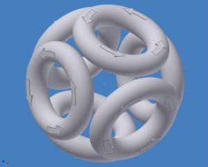 Here is the virtual coil shown overlaid on it:
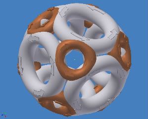
A similar field configuration would result if the 6 cube coils were replaced with 8 coils at the corners where the virtual coils are.
The original coils would now be the virtual coils.
Like this: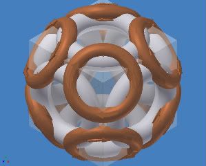 Or finally this:
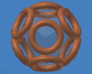
It is now an octahedron.
It still has funny cusps but they have swapped places with the cube coil centers.
If you look at the top there is a square-ish virtual coil.
If you look at the brown coils they could be triangular.
When I look at it that way I see MPG-1. (With a little rewiring sort of like magnetic field line reconnection)
Interesting Eh?
The square coils and triangular coils have opposite polarity.
Now THAT fits with Dr Bussard’s original description.
An octahedron does have the property of an even number (4) of faces around each vertex.
He said that MPG-1 & 2 had good properties and even measured D-D fusion.
The only problem (mentioned) was that he could not drive enough current through them.
I’m not surprised considering they look like only quarter inch diameter copper tube.
I think the MPG’s were on the right path.
Half the flux through the polyhedral surface must be out and half must be in. (ref. Maxwell)
Here is how I see Dr. Bussard's original thought process.
He started with a 2 coil cusp machine.
It has stability, but is has that huge loss equator.
Then he added 2 more pairs of coils around the equator pushing the remnants of the equatorial cusp to the corners of the cube.
When I look at the corner of the cube I see a virtual coil made from the 3 segments of coil closest to it.
Here is the corner:
Here is the virtual coil shown overlaid on it: A similar field configuration would result if the 6 cube coils were replaced with 8 coils at the corners where the virtual coils are.
The original coils would now be the virtual coils.
Like this:
Or finally this: It is now an octahedron.
It still has funny cusps but they have swapped places with the cube coil centers.
If you look at the top there is a square-ish virtual coil.
If you look at the brown coils they could be triangular.
When I look at it that way I see MPG-1. (With a little rewiring sort of like magnetic field line reconnection)
Interesting Eh?
The square coils and triangular coils have opposite polarity.
Now THAT fits with Dr Bussard’s original description.
An octahedron does have the property of an even number (4) of faces around each vertex.
He said that MPG-1 & 2 had good properties and even measured D-D fusion.
The only problem (mentioned) was that he could not drive enough current through them.
I’m not surprised considering they look like only quarter inch diameter copper tube.
I think the MPG’s were on the right path.
-Tom Boydston-
"If we knew what we were doing, it wouldn’t be called research, would it?" ~Albert Einstein
"If we knew what we were doing, it wouldn’t be called research, would it?" ~Albert Einstein
Hmm, that's a very nice rendering! I'd tried to visualize the corners like that, as virtual coils, but I never got anywhere with it. IIRC, there'd always be one corner where the 'brown' virtual coil had two flows going one direction and one going the opposite way.
That 'octahedron' at the bottom looks funny; I don't think that's technically an octahedron, althought it has eight coils. And those corner cusps have a lot of area.
That 'octahedron' at the bottom looks funny; I don't think that's technically an octahedron, althought it has eight coils. And those corner cusps have a lot of area.
This was not intended as an actual configuration.
Just a concept visualization.
Yes AutoCAD does nice rendering. This is just its default mode.
The flows actually do all line up nicely on all coils.
I just double checked them.
The coils are on the vertexes of a cube aligned with the center.
I'm pretty sure that puts them on a regular octahedron.
Yes, octahedrons do look funny, not quite like you would expect, even lopsided from some angles.
-Tom Boydston-
"If we knew what we were doing, it wouldn’t be called research, would it?" ~Albert Einstein
"If we knew what we were doing, it wouldn’t be called research, would it?" ~Albert Einstein
rcain,
As an engineer my focus is on knowing enough of how everything works to build a working reactor.
We are a ways from there yet. The WB-7 experiments are just a start.
I think most of the folks here are cautiously optimistic. Which is a good attitude. Rational cheer leading vs. blind optimism. There are known problems. We like to discuss them to see if we can find solutions.
Engineering is the art of making what you want from what you can get at a profit.
Tombo,
Exactly ... you can do the truncube with eight instead of six magnets. Going back into one of Dr. Bussard's papers I found that he had realized the same thing.
He toyed with the idea of small magnets on the corners of a closed-box machine, and I would not be surprised if WB5's chamber had provisions to try them. It was awfully complex-looking compared to PXL-1
Tombo another thing I didn't see you mention is that with the 8-coil cube configuration you only have 3 connection points between each coil, as opposed to 4 for each with the 6-coil trunc cube. In addition, they're in a "tripod" equilateral triangle arrangement, which is naturally stronger...interesting! you may have discovered the optimal truncated cube coil arrangement!tombo wrote: <snip>
A similar field configuration would result if the 6 cube coils were replaced with 8 coils at the corners where the virtual coils are.
The original coils would now be the virtual coils.
Like this:
It is now an octahedron.
It still has funny cusps but they have swapped places with the cube coil centers.
If you look at the top there is a square-ish virtual coil.
If you look at the brown coils they could be triangular.
When I look at it that way I see MPG-1. (With a little rewiring sort of like magnetic field line reconnection)
Interesting Eh?
The square coils and triangular coils have opposite polarity.
Now THAT fits with Dr Bussard’s original description.
An octahedron does have the property of an even number (4) of faces around each vertex.
He said that MPG-1 & 2 had good properties and even measured D-D fusion.
The only problem (mentioned) was that he could not drive enough current through them.
I’m not surprised considering they look like only quarter inch diameter copper tube.
I think the MPG’s were on the right path.
On second thought, either way it will be 12 connections...hmm.
Tom.Cuddihy
~~~~~~~~~~~~~~~~~~~~~
Faith is the foundation of reason.
~~~~~~~~~~~~~~~~~~~~~
Faith is the foundation of reason.
Good. Thank You.
The shape of the virtual coils in any configuration with circular toroidal coils is a funny concave shape that I see as a problem.
Now as I see it, the confinement of any individual mirror is independent of the field direction (in or out).
So combine this with the MPG concept.
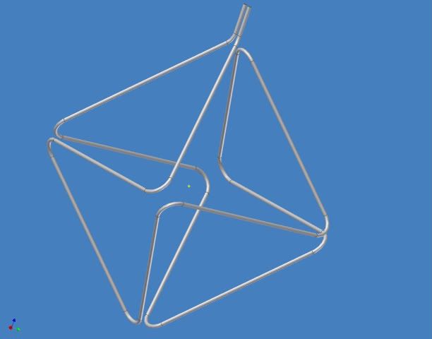
I would like to propose a Magrid configuration:
Consider the octahedral configuration.
It is the simplest polyhedron that meets the patent requirements.
This configuration has half as many poles as the truncated octahedron=truncated cube.
But the field lines are still everywhere convex toward the plasma.
This configuration meets the patent geometry requirements with an even number of faces around each vertex and an in-out-in-out field orientation.
Advantages over cube or dodecahedron with toroidal coils:
The field lines naturally conform to all the material surfaces.
This configuration does away with the funny cusps since all the faces are the same.
There are no concave coils or virtual coils.
Note the Eulerian path.
The field lines vary smoothly from point to point everywhere.
There are no null fields as the field reverses direction only at coils.
There is no need for electrical connections between coils within the vacuum chamber.
The feed lines are shielded by the full current of the Magrid.
Coolant can flow smoothly through the whole coil assembly.
There is no need for coolant joints inside the vacuum chamber.
The coil could be full of wires connected outside the chamber to form a coil, but I prefer to make it in one coil made of copper tubing with coolant flowing through it.
The points where the adjacent loops come near each other have the sharpest bends and the closest spacing so the highest fields occur exactly where mechanical ties might be needed. I’m thinking quartz fiber ties.
The field would be even higher at that spot than for a set of round coils (WB6, WB7) because of the smaller local radius. Ie. It looks like a smaller coil of the same current from up close.
This geometry can be fabricated in a straightforward manner.
The tubes can possibly be thick enough to be free standing.
I have experience using water cooled copper tubing as power conductors in RF induction furnaces.
The technology is tried and true. It works very well, so well that one of the problems was condensation from too much cooling.
I prefer the one turn configuration because:
The field is due to the amp-turns so 200 turns at 1000 amps (WB6) makes the same field as one turn at 200,000 amps.
The resistance losses are the same too, because power loss goes up as the square of the current and the resistance goes down as the square of the wire radius.
So trading turns for current is a wash for resistance losses as long as the total conductive cross section is the same.
One turn is better for keeping the field lines conformed to the material surfaces.
One turn is better because there are no packing factor losses and no insulation taking up space or failing.
One turn is worse for feed line losses. But, this is balanced by the magnetic shielding of the feed lines.
Also, these resistance considerations go away when we get to superconductors.
One turn gives less complexity inside the chamber and more complexity outside the chamber in the form of a higher current power supply.
A good EE should have no problem solving that. (I really wanted to use a tongue-in-cheek but it isn’t available)
Moving the complexity to the outside of the vacuum chamber counts as a good move in my book.
I think a low duty cycle experimental device with simple water cooled standard sized copper tubing could prove the configuration and prove the Polywell concept.
It would recover between shots very quickly.
Also, it would be easy to make.
I have built much more complicated bent-tube piping systems.
I think the MPG’s were on the right track. They worked well and even made DD fusions.
They just needed much more current.
But wait it gets better:
Consider:
This configuration can move 4 times a much heat out of the chamber.
It also is mechanically stronger and more stable.
The parts are very simple and easy to make.
Also note the quadrupole between the feed lines.
That looks like a null B field along that line.
It could be a particle escape path. But it should not be too bad because it is so long compared to its width.
But in addition to an escape path I think it could be a path along which to carefully aim an electron gun and an ion gun for particle injection.
The feed lines should be configured and spaced to coordinate with the injection guns, to create impedance matched RF feed lines (for POPS mode) and to place them in the coil’s particle & radiation shadow.
Question for the particle gun guys and the RF guys:
Does it really work this way or am I barking up the wrong tree?
I will make shop drawings if anyone has the resources to build it.
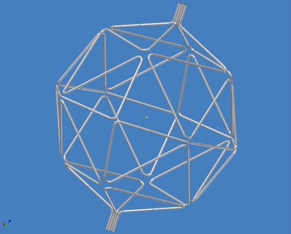
It even seems to work if we need to build up the conductors to 8” diameter to accommodate many layers of insulation and various temperature cooling passages.
Here is what it looks like for a 2 meter diameter Polywell with 8 inch thick coils.
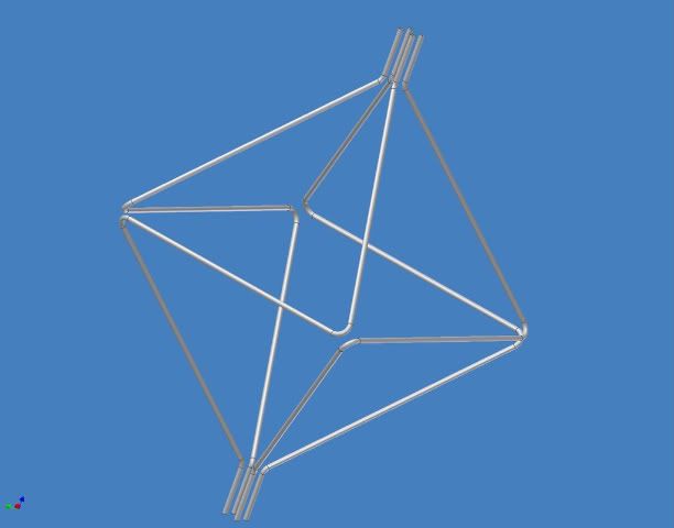
OK. Now if that works and if we don’t need 8” thick pipes, here is a further refinement:
Same showing only 1 of the 4 circuits:
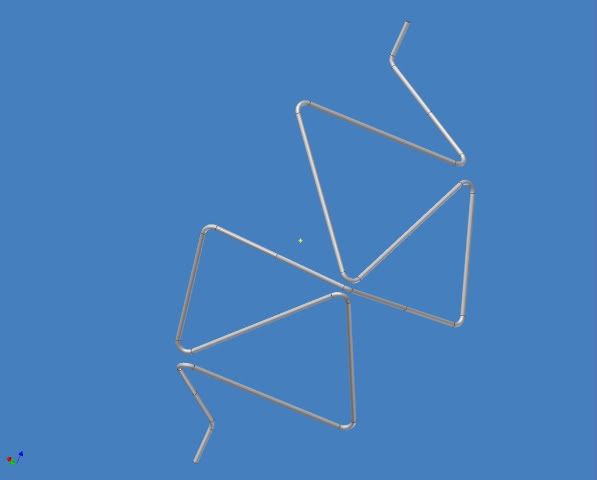
This shows the octahedron modified to add a triangular loop inside each triangular coil making it a 32-hedron. (I call it an 8x4-hedron.)
It breaks each of the octahedron’s triangular faces into 4 triangular faces.
The fields in adjacent faces are still alternating and smooth and convex toward the plasma inside with no null fields, except between the feed lines.
It makes the device closer to a sphere, which I intuitively think is a good thing.
Here are some rationalizations for 32 faces being better than 8 faces:
1. The 32 face configuration reduces the current by a factor of 4 to create the same magnetic field. (This assumes that a triangular coil scales like a circular coil.)
2. It has a smoother field.
3. The same reasons that WB7 is a dodecahedron rather than a cube.
4. There is a larger volume of low field in the center creating larger well volume.
Is this true and is it actually a good thing?
5. There is less mechanical force on the coils.
The forces parallel to the surface of the sphere cancel out and the only total force on a segment is a radial force which is a fraction of the total force so each segment of tube does not need to be as strong.
This advantage does not apply to the coil ties. The ties being parallel to the sphere surface see the full force.
The ties are not shown but might need to be installed at some or all of the sharp bends to resist the mechanical forces trying to expand the sphere.
6. The water flow volume even through this many bends is still sufficient to carry away a prodigious amount of heat, especially if the flow rate is pushed high enough to shorten part life with erosion pitting etc.
(I don’t believe my own numbers so I won’t say them. I need a second opinion here.)
But, for an empirical anchor: At 46 minutes into the Google video the MPG’s show about ¼” diameter tubes & Dr Bussard says they were limited by steam to 2kAmp.
Going from 1/4” tube to 1” tube decreases the resistance by factor of 8, increases flow cross section by a factor of 23. Assuming their flow speed I get a total increase of 188 times to a total of 377kA, which is well beyond the 200kA preliminary target.
This is all for standard wall tubing.
If we go to thicker wall and OFHC copper the cooling load will decrease.
Also, I have fewer bends in each circuit to restrict water flow than MPG-1.
Also, the larger tube will have a smaller friction coefficient.
So I am in the ballpark.
I need to work on my water flow model. It is not quite right.
Also I need to calculate the heat flow through the bulk copper and across the interface into the coolant.
But, in any case it should be good enough for a sufficiently low shot rate in the experimental model.
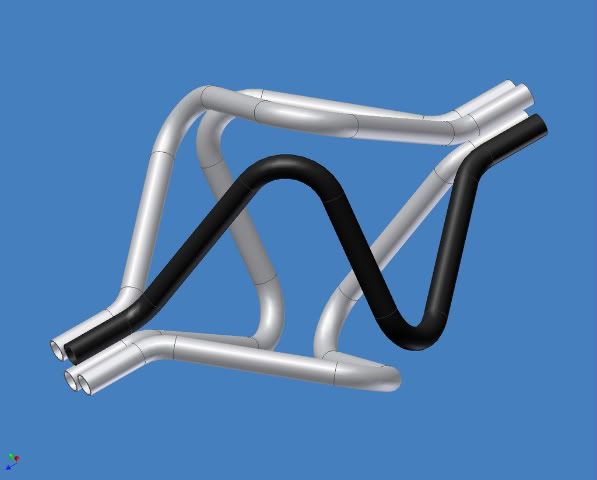
The next refinement is to add yet another triangular coil inside each triangular coil:
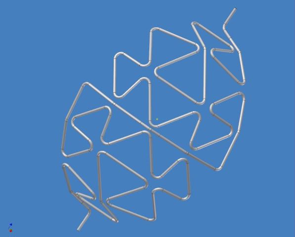
I show only one quarter of it to reduce visual clutter.
This is even closer to a sphere and increases the advantages above.
This process can be extended indefinitely to make 128-gons, 512-gons, 2048-gons etc.
It is similar to a Sierpinski triangle. But, it is harder to make because all the triangles of a given size need to be filled in.
We have to stop somewhere due to increased coolant flow resistance.
If needed, we could increase the number of circuits to 8 or more to mitigate this but at some point complexity overwhelms us.
These parts could be mass produced on a 4-slide machine.
In fact, I think that if they were simple copper tubes they would be cheap enough to be consumable parts.
Further Refinements:
I think the outside of the tube needs a plating to reduce out-gassing and to enhance thermal reflectivity.
Perhaps that would be bright-nickel, chromium, gold or boron (for neutrons and heat).
I think it might be possible to deposit a superconductor on the inside of the tube using electroplating, thermal deposition or CVD after fabrication.
But this is whole new problem of its own that could easily become a distraction from this effort. Probably worth a PhD to someone though if they can do it and widely applicable.
I’m pretty sure Hyper Tech Research's CTFF process could be modified to incorporate a coolant tube down the centerline of the superconducting wire.
I also have many further details in mind but the basic concept must work first.
Concerns:
1. What does the field look like inside a triangular turn?
Specifically what is the minimum field at the center? I can’t solve it. I’ve done all my calculations based on assuming it to be like a circular coil of the same size.
2. What does the field look like between turns where they come close together?
More to the point what is the particle flux in this vicinity where the mechanical ties would need to be?
3. How well do the field lines conform to the tube in the vicinity of the sharp bends?
4. How is the overall field shaped?
5. How does the electron recirculation work with this field shape?
5. a) Is it a problem having the opposite faces with different polarities as long as the field is everywhere convex toward the plasma?
5. b) Is it better to have the field line arches penetrate deeply into the center creating a gradient further into the well or is it better to have them stay closer to the magrid sphere leaving a larger flatter well? This affects the choice of the number of faces.
6. Some triangles are equilateral and some are 45-90.
This difference may be a problem. If it is, the problem might be reduced by equalizing the triangle areas.
But I think it will be less of a problem than the in-bending triangles of the virtual coils at the cube corners of a standard PW.
7. Thermal issues need to be fleshed out.
8. Mechanical stress details need to be fleshed out.
9. Chamber wall feed-throughs need to sorted out.
10. The field and plasma modeling are beyond me.
11. The usual problems. I.e. all the things that I did not see coming.
Thank you for reading this far.
I’m hoping that some of you will find this design intriguing enough to give it serious consideration.
The shape of the virtual coils in any configuration with circular toroidal coils is a funny concave shape that I see as a problem.
Now as I see it, the confinement of any individual mirror is independent of the field direction (in or out).
So combine this with the MPG concept.
I would like to propose a Magrid configuration:
Consider the octahedral configuration.
It is the simplest polyhedron that meets the patent requirements.
This configuration has half as many poles as the truncated octahedron=truncated cube.
But the field lines are still everywhere convex toward the plasma.
This configuration meets the patent geometry requirements with an even number of faces around each vertex and an in-out-in-out field orientation.
Advantages over cube or dodecahedron with toroidal coils:
The field lines naturally conform to all the material surfaces.
This configuration does away with the funny cusps since all the faces are the same.
There are no concave coils or virtual coils.
Note the Eulerian path.
The field lines vary smoothly from point to point everywhere.
There are no null fields as the field reverses direction only at coils.
There is no need for electrical connections between coils within the vacuum chamber.
The feed lines are shielded by the full current of the Magrid.
Coolant can flow smoothly through the whole coil assembly.
There is no need for coolant joints inside the vacuum chamber.
The coil could be full of wires connected outside the chamber to form a coil, but I prefer to make it in one coil made of copper tubing with coolant flowing through it.
The points where the adjacent loops come near each other have the sharpest bends and the closest spacing so the highest fields occur exactly where mechanical ties might be needed. I’m thinking quartz fiber ties.
The field would be even higher at that spot than for a set of round coils (WB6, WB7) because of the smaller local radius. Ie. It looks like a smaller coil of the same current from up close.
This geometry can be fabricated in a straightforward manner.
The tubes can possibly be thick enough to be free standing.
I have experience using water cooled copper tubing as power conductors in RF induction furnaces.
The technology is tried and true. It works very well, so well that one of the problems was condensation from too much cooling.
I prefer the one turn configuration because:
The field is due to the amp-turns so 200 turns at 1000 amps (WB6) makes the same field as one turn at 200,000 amps.
The resistance losses are the same too, because power loss goes up as the square of the current and the resistance goes down as the square of the wire radius.
So trading turns for current is a wash for resistance losses as long as the total conductive cross section is the same.
One turn is better for keeping the field lines conformed to the material surfaces.
One turn is better because there are no packing factor losses and no insulation taking up space or failing.
One turn is worse for feed line losses. But, this is balanced by the magnetic shielding of the feed lines.
Also, these resistance considerations go away when we get to superconductors.
One turn gives less complexity inside the chamber and more complexity outside the chamber in the form of a higher current power supply.
A good EE should have no problem solving that.
Moving the complexity to the outside of the vacuum chamber counts as a good move in my book.
I think a low duty cycle experimental device with simple water cooled standard sized copper tubing could prove the configuration and prove the Polywell concept.
It would recover between shots very quickly.
Also, it would be easy to make.
I have built much more complicated bent-tube piping systems.
I think the MPG’s were on the right track. They worked well and even made DD fusions.
They just needed much more current.
But wait it gets better:
Consider:
This configuration can move 4 times a much heat out of the chamber.
It also is mechanically stronger and more stable.
The parts are very simple and easy to make.
Also note the quadrupole between the feed lines.
That looks like a null B field along that line.
It could be a particle escape path. But it should not be too bad because it is so long compared to its width.
But in addition to an escape path I think it could be a path along which to carefully aim an electron gun and an ion gun for particle injection.
The feed lines should be configured and spaced to coordinate with the injection guns, to create impedance matched RF feed lines (for POPS mode) and to place them in the coil’s particle & radiation shadow.
Question for the particle gun guys and the RF guys:
Does it really work this way or am I barking up the wrong tree?
I will make shop drawings if anyone has the resources to build it.
It even seems to work if we need to build up the conductors to 8” diameter to accommodate many layers of insulation and various temperature cooling passages.
Here is what it looks like for a 2 meter diameter Polywell with 8 inch thick coils.
OK. Now if that works and if we don’t need 8” thick pipes, here is a further refinement:
Same showing only 1 of the 4 circuits:
This shows the octahedron modified to add a triangular loop inside each triangular coil making it a 32-hedron. (I call it an 8x4-hedron.)
It breaks each of the octahedron’s triangular faces into 4 triangular faces.
The fields in adjacent faces are still alternating and smooth and convex toward the plasma inside with no null fields, except between the feed lines.
It makes the device closer to a sphere, which I intuitively think is a good thing.
Here are some rationalizations for 32 faces being better than 8 faces:
1. The 32 face configuration reduces the current by a factor of 4 to create the same magnetic field. (This assumes that a triangular coil scales like a circular coil.)
2. It has a smoother field.
3. The same reasons that WB7 is a dodecahedron rather than a cube.
4. There is a larger volume of low field in the center creating larger well volume.
Is this true and is it actually a good thing?
5. There is less mechanical force on the coils.
The forces parallel to the surface of the sphere cancel out and the only total force on a segment is a radial force which is a fraction of the total force so each segment of tube does not need to be as strong.
This advantage does not apply to the coil ties. The ties being parallel to the sphere surface see the full force.
The ties are not shown but might need to be installed at some or all of the sharp bends to resist the mechanical forces trying to expand the sphere.
6. The water flow volume even through this many bends is still sufficient to carry away a prodigious amount of heat, especially if the flow rate is pushed high enough to shorten part life with erosion pitting etc.
(I don’t believe my own numbers so I won’t say them. I need a second opinion here.)
But, for an empirical anchor: At 46 minutes into the Google video the MPG’s show about ¼” diameter tubes & Dr Bussard says they were limited by steam to 2kAmp.
Going from 1/4” tube to 1” tube decreases the resistance by factor of 8, increases flow cross section by a factor of 23. Assuming their flow speed I get a total increase of 188 times to a total of 377kA, which is well beyond the 200kA preliminary target.
This is all for standard wall tubing.
If we go to thicker wall and OFHC copper the cooling load will decrease.
Also, I have fewer bends in each circuit to restrict water flow than MPG-1.
Also, the larger tube will have a smaller friction coefficient.
So I am in the ballpark.
I need to work on my water flow model. It is not quite right.
Also I need to calculate the heat flow through the bulk copper and across the interface into the coolant.
But, in any case it should be good enough for a sufficiently low shot rate in the experimental model.
The next refinement is to add yet another triangular coil inside each triangular coil:
I show only one quarter of it to reduce visual clutter.
This is even closer to a sphere and increases the advantages above.
This process can be extended indefinitely to make 128-gons, 512-gons, 2048-gons etc.
It is similar to a Sierpinski triangle. But, it is harder to make because all the triangles of a given size need to be filled in.
We have to stop somewhere due to increased coolant flow resistance.
If needed, we could increase the number of circuits to 8 or more to mitigate this but at some point complexity overwhelms us.
These parts could be mass produced on a 4-slide machine.
In fact, I think that if they were simple copper tubes they would be cheap enough to be consumable parts.
Further Refinements:
I think the outside of the tube needs a plating to reduce out-gassing and to enhance thermal reflectivity.
Perhaps that would be bright-nickel, chromium, gold or boron (for neutrons and heat).
I think it might be possible to deposit a superconductor on the inside of the tube using electroplating, thermal deposition or CVD after fabrication.
But this is whole new problem of its own that could easily become a distraction from this effort. Probably worth a PhD to someone though if they can do it and widely applicable.
I’m pretty sure Hyper Tech Research's CTFF process could be modified to incorporate a coolant tube down the centerline of the superconducting wire.
I also have many further details in mind but the basic concept must work first.
Concerns:
1. What does the field look like inside a triangular turn?
Specifically what is the minimum field at the center? I can’t solve it. I’ve done all my calculations based on assuming it to be like a circular coil of the same size.
2. What does the field look like between turns where they come close together?
More to the point what is the particle flux in this vicinity where the mechanical ties would need to be?
3. How well do the field lines conform to the tube in the vicinity of the sharp bends?
4. How is the overall field shaped?
5. How does the electron recirculation work with this field shape?
5. a) Is it a problem having the opposite faces with different polarities as long as the field is everywhere convex toward the plasma?
5. b) Is it better to have the field line arches penetrate deeply into the center creating a gradient further into the well or is it better to have them stay closer to the magrid sphere leaving a larger flatter well? This affects the choice of the number of faces.
6. Some triangles are equilateral and some are 45-90.
This difference may be a problem. If it is, the problem might be reduced by equalizing the triangle areas.
But I think it will be less of a problem than the in-bending triangles of the virtual coils at the cube corners of a standard PW.
7. Thermal issues need to be fleshed out.
8. Mechanical stress details need to be fleshed out.
9. Chamber wall feed-throughs need to sorted out.
10. The field and plasma modeling are beyond me.
11. The usual problems. I.e. all the things that I did not see coming.
Thank you for reading this far.
I’m hoping that some of you will find this design intriguing enough to give it serious consideration.
-Tom Boydston-
"If we knew what we were doing, it wouldn’t be called research, would it?" ~Albert Einstein
"If we knew what we were doing, it wouldn’t be called research, would it?" ~Albert Einstein