Page 1 of 3
FUSION 3D ART
Posted: Tue May 06, 2008 11:10 pm
by Torulf2
Hi my name is Torulf Greek. I’m a biologist and 3D amateur from Sweden.
In some other treads its have been questions about 3D software, shoving of poly-art and debate of different alternatives for fusion energy. But I start a new tread about this.
I have made illustrations and animations for the Focus Fusion Society, and to Eric Learners Google talks.
http://focusfusion.org/log/index.php
http://video.google.com/videoplay?docid ... 9479871760
The plasma focus been known in long time to be sores for fusion neutrons. But it has been neglected by funding in same way as the IEC fusion. I can not decide if the tokamak is going to works or not. But it probably comes too late for save us from energy crises and greenhouse warming. No one knows which fusion devise how will work, if any. It is necessary to have diversity in the research.
For the pictures and animations I use Cinema 4D. It’s professional 3d software. C4D powerful but not the most complete of these apps but that one how is quickest to learn and easiest to use.
http://www.maxon.net/pages/dyn_files/dy ... ome_e.html
A movie shoving the sequence in a plasma focus. Observe, the details about how the plasmoids are formed is unknown.
http://s246.photobucket.com/albums/gg11 ... 3aDind.flv
The movie also is here on Youtube.
http://www.youtube.com/watch?v=Byf5_e2W8Hs
The boron proton reaction.
The Z-machine.
A cylindrikal plasma focus devise.
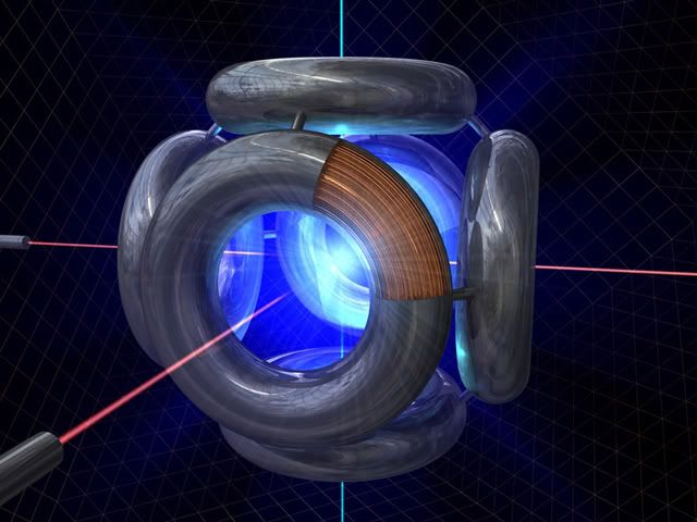
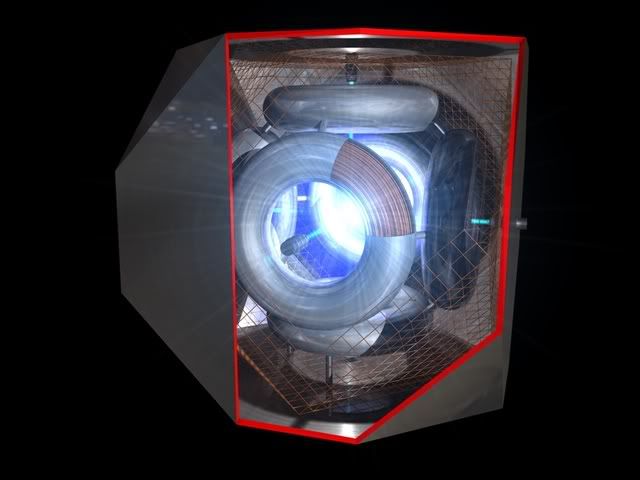
Work in progress of the Polywell.
I have more pictures here.
http://www.flickr.com/photos/26105710@N05/
I’m grateful for comments and constructive critics, special the Polywell. How shall the he arrangements of the electron guns and the ion-guns look like? Electron rays in read and ion rays in blue in the pictures.
The pictures and animations are free for use for promotion of respective fusion methods.
If someone ask referrer to me.
MAIL: Torulfgreek(2)yahoo.se
PS. I do not know how to do for make the pictures show up here.
Please tell me.
==
Edited to make the picture show up M. Simon - you left out the closing tag.
[ /img ] - no spaces Also no period before h t t p
Posted: Tue May 06, 2008 11:35 pm
by MSimon
Fixed your images.
Posted: Wed May 07, 2008 12:44 am
by Tom Ligon
Pleased to have you here. Your work is stunning!
I'm somewhat familiar with the Focus Fusion effort, and curious if it derives from Paul Koloc's spheromak ideas. I have no opinion one way or another if it can burn p-B11 above unity, but if it is based on inducing spheromaks I can believe it can do at least some fusion. Dr. Bussard himself was intrigued by the possiblity.
I ran into their website when they had a short and quite respectful bit of news about Dr. Bussard's effort. Consequently, I have nothing bad to say about them.
Posted: Wed May 07, 2008 3:31 am
by drmike
Nice graphics!! Thanks for posting it here.
Similar Theme
Posted: Wed May 07, 2008 5:27 am
by PolyGirl
Have a look at this thread as well.
Polywell Art
Regards
Polygirl
Posted: Wed May 07, 2008 11:56 am
by tonybarry
Hello Torulf,
Your pix are great stuff. Please keep them coming.
I note from the polywell picture "Work in progress on the Polywell" that Torulf has the electron / ion guns' discharge entering through the centre hole in the MaGrid. Is this correct, or does the ion stream enter at forty-five degrees to this hole - i.e. where three donuts form a corner?
Regards,
Tony Barry
Posted: Wed May 07, 2008 12:19 pm
by Keegan
Welcome aboard Torulf2 !
Nice work. I have been giving myself a crash course in CAD lately.
Just wondering does Cinema 4d support parametric modeling ?
^ Tony i think ion/electron gun placement is either/or. I hypothesized that the corner cusps could be superior (and hence used in WB6) because of choked flow. Its probably not worth getting too fused about.
Fuel Ionization and Alpha particles leaving behind electrons largely drives the reactor.
Also Tom L pointed out that you really wouldn't "see" a wiffle ball as such. Only flashes when atoms recombine, which is bad. Still i dont mind people using every ounce of their creative license

Posted: Wed May 07, 2008 1:09 pm
by drmike
tony - I really would like to know which placement is "better". My bet is that the answer is "better for what?" - i.e. it will depend on what is more important over the long run.
Keegan - I'm not so sure a nozzle is a good analogy. You get rotation of the beam in a B field, so the nozzle acts like a mirror. The cusps will have tighter focus so will be better mirrors. If all the electron velocities are within the loss cone, it may not matter. It will be great to do a lot of experiments!
Torulf2 - Keep up the great work! It definitely helps get the idea across.
Posted: Wed May 07, 2008 7:47 pm
by Tom Ligon
Keegan,
I'm no longer sure I'm correct about that assertion you can't see the wiffleball.
That was my working assumption when we did video and PMT studies of PXL-1 and WB3. In those, we did not have enough power supply to hold the voltage up during the bright events, and I was finding we had the deepest potential wells when there was little or no light output. The really bright glows tended to pull the voltage down too far for any hope of fusion. However, the bright events did frequently show the topology of a wiffleball.
From what Dr. Nebel has been saying, fusion conditions exist in the newer experiments at densities far higher than I expected. You still want to avoid runaway density, and I'd guess light output is still an indication of loss of ions, but they're driving with a lot more power than I ever had available, and can stand more recombination.
Posted: Wed May 07, 2008 10:19 pm
by TallDave
Those are really beautiful. You even got the p-b11 reaction right! My hat is off to you.
Maybe you could posterize/T-shirt-ize some of them on CafePress. I know I wouldn't mind having a couple around.
From what Dr. Nebel has been saying, fusion conditions exist in the newer experiments at densities far higher than I expected
That's certainly interesting.
Posted: Thu May 08, 2008 7:54 am
by tonybarry
Hello Dr. Mike,
Would it be that the positive species enter through the three-ring corner cusp and the negative species enter through the centre of the ring? Depending on the direction of electron flow? If electrons circulate then pushing them in the same direction of flow ought to have some effect (perhaps minimal as they have small mass), but pushing positive species in the same direction will have a much greater effect.
Unfortunately I am not yet able to answer this myself

Regards,
Tony Barry
Re: FUSION 3D ART
Posted: Thu May 08, 2008 9:57 am
by djolds1
Torulf2 wrote:
Hi my name is Torulf Greek. I’m a biologist and 3D amateur from Sweden.
In some other treads its have been questions about 3D software, shoving of poly-art and debate of different alternatives for fusion energy. But I start a new thread about this.
Good Lord is this beautiful work. Kudos.
Duane
Posted: Thu May 08, 2008 1:51 pm
by JohnP
Noticed that the coils in the above animated polywell are sort of pentagonal, not circular. Does that matter - should they be one way or the other?
Posted: Thu May 08, 2008 2:01 pm
by drmike
tonybarry wrote:Hello Dr. Mike,
Would it be that the positive species enter through the three-ring corner cusp and the negative species enter through the centre of the ring? Depending on the direction of electron flow? If electrons circulate then pushing them in the same direction of flow ought to have some effect (perhaps minimal as they have small mass), but pushing positive species in the same direction will have a much greater effect.
Unfortunately I am not yet able to answer this myself
Regards,
Tony Barry
So far I've been trying to deal with just electrons, not whole plasma. I don't think you can separate species very far other than in a sheath region. For a whole plasma, both cusp areas should have about equal density of charge - not more than 1e-4 difference at the most.
Electrons follow field lines really well - the gyro radius is 2.4*sqrt(T)/B (here is a
great page of plasma parameters), so strong fields and light electrons make them spin really tight. Only those with high parallel velocity will get past the mirror.
I think an ion rocket engine will work for either the cusp or the coil face, but I like the coil face for injection because the field is more symmetric. It could be that Bussard put the electron emitters at the cusps to help plug the loss cone, and the use of starting the plasma there was secondary.
In any case, I think you want to maintain neutrality so the system will be stable. Fortunately, that's easy to do.
Posted: Thu May 08, 2008 3:25 pm
by Tom Ligon
The original models, thru WB3 at least, put the emitters on faces instead of corners. I believe they switched to corners because the external electrostatic configuration is a bit better for electron extraction from the emitters. Once the electrons are doing their thing, I think it is pretty much six of one, half a dozen of the other.
The Tony Rusi/Skip Baker Dodec showed the pentagon magnets, I think based on a misunderstanding of the description of the geometry. The MPG machines (copper tubing) would have been made that way, and I can't think of any good reason it would not work. Circular magnets such as you see on WB6 would almost certainly be easier to fabricate in a multi-turn wire wound machine, and should avoid stress concentrations at the bends. This model is ambiguously in-between, and I think it is perfectly fine.