dodecahedron
dodecahedron
It has been said that Dr. Bussard had envisioned that WB-8 would be a dodecahedron. In evaluating funding priorities, would that still be the most logical next design step for WB-8? What might be the potential advantages of a dodecahedron design over the present WB-7 design? What might be its shortcomings?
There's a lot of information right here on the forums.. If you search for dodecahedron, you get these:
viewtopic.php?t=289&highlight=dodecahedron
viewtopic.php?t=593&highlight=dodecahedron
viewtopic.php?t=462&highlight=dodecahedron
viewtopic.php?t=357&highlight=dodecahedron
viewtopic.php?t=319&highlight=dodecahedron
viewtopic.php?t=289&highlight=dodecahedron
viewtopic.php?t=593&highlight=dodecahedron
viewtopic.php?t=462&highlight=dodecahedron
viewtopic.php?t=357&highlight=dodecahedron
viewtopic.php?t=319&highlight=dodecahedron
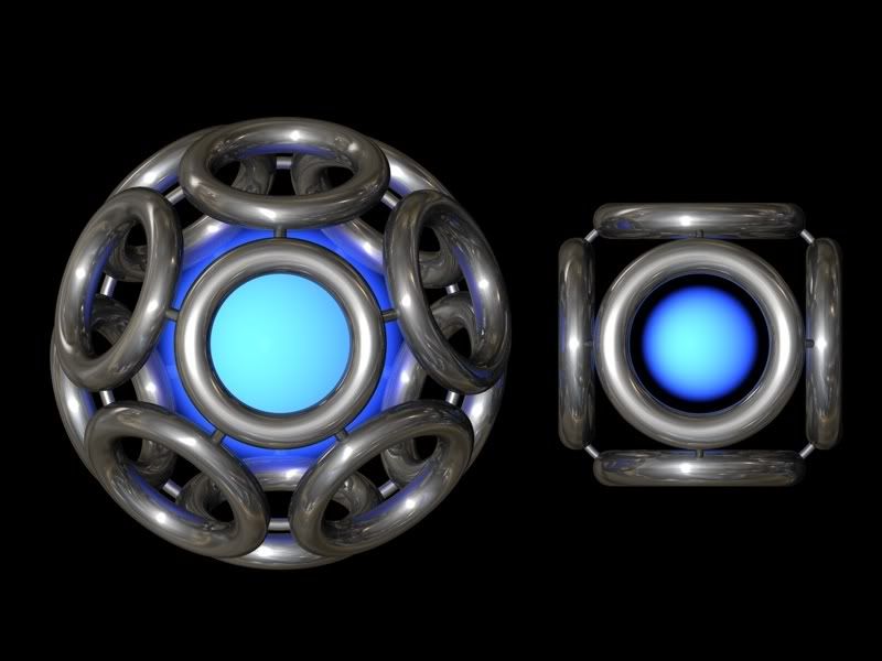
The dodecahedral polywell have bigger diameter and volume compared to the cubic polywell.
If the coils have same size the distance from the coils to the core becomes significant grater for the dodecahedral configuration compared to the cubic. This should give weaker magnetic field in the core. Can this deteriorate the waffleball in the dodecahedral configuration?
Link to picture.
[img] http://i246.photobucket.com/albums/gg11 ... mmetry.jpg [/img ]
HTML
<a href="http://s246.photobucket.com/albums/gg11 ... mmetry.jpg" target="_blank"><img src="http://i246.photobucket.com/albums/gg11 ... mmetry.jpg" border="0" alt="IEC polywell BFR fusion energy nuklear"></a>
-
blaisepascal
- Posts: 191
- Joined: Thu Jun 05, 2008 3:57 am
- Location: Ithaca, NY
- Contact:
Welcome! I'm not a physics great either, but I've hung around here a bunch and I hope I can answer your questions, at least to the best of my ability.Colonel_Korg wrote:I'n new to this forum and my physics is quite rusty, so please forgive me if theses questions have already been asked (I looked and didn't see any quite like them),
Others may correct me, but I'd say yes-and-no.Question 1: During his google talk, Dr Bussard mentioned that the coils to form the polywell should be an even number at the cusps so that the magnetic fields on any two ajacent coils could be opposit? Am I wrong on this?
My understanding of that even-numbered criterion was that that applied to the polyhedron the polywell was based on. The idea is to have each face of the polyhedron be a solonoid, and each edge of the polyhedron be a conductor. The magnetic field should also be as symmetric as possible.
In order for this to work, the direction of current on each edge must be such that each face forms a loop. A moments reflection shows that this also means that the direction (clockwise/counterclockwise) of the current loop on each face must be opposite for faces which share an edge. The polarity of adjacent faces is reversed.
The latter is what causes the "even number" criterion Dr. Bussard was talking about. Requiring no two adjacent faces to have the same polarity is the same as saying that the underlying polyhedron can be two-colored: each face is red or blue, and no two adjacent faces have the same color. If you look at any vertex of the polyhedron, it's easy to see that all the vertices must have an even number of edges going into it. If you had an odd number, then you must have two adjacent faces of the same polarity.
You can see this with the platonic solids: It's impossible to two-color the faces of a tetrahedron, cube, dodecahedron, or icosahedron because the order of their vertices are 3, 3, 3, and 5 respectively. It's possible to two-color an octohedron, and it's vertices are of order 4.
This does suggest the question: If it's impossible to two-color a cube, if a cube fails Dr. Bussard's even-number of coils around a cusp issue, then why are the polywell designs people are talking about cubes? Or dodecahedrons, which also fail that criterion.
The answer is that it isn't really a "cube", for the purpose of Bussard's analysis. The 6 physical coils also make 8 "virtual coils", with opposite polarity, centered around the vertices of the cube. The only place you have two coils of the same polarity approaching each other is along the edges of the cube, where two virtual coils and two physical coils "meet". So the underlying polyhedral structure of the WB-6 (And WB-7) isn't cubical, but rather cuboctahedral. A cuboctahedron has 6 square faces, 8 triangular faces, and 12 vertices, each of which is of order 4, which meets Dr. Bussard's evenness criterion.
As far as cusps go, the cuboctahedron has 24 cusps, one for each face, and one for each vertex. In the polywell, the cusps corresponding to the vertices are the dreaded "line cusps", where high electron losses are traditionally suspected of coming from, while the cusps corresponding to faces are "point cusps". So one way of describing what Bussard was talking about is that an even number of coils, physical and virtual, must meet at each line cusp.
If you look at it with the same sort of analysis I applied to the cube, you'll find that it has 8 physical coils, 6 virtual coils, and 12 places where coils come together, in exactly the same configuration as a cuboctahedron. The difference between it and that of the "standard" cubical polywell is the swapping of physical and virtual coils.If I'm right, I have not seen this configuration of 8 coils in an octahedron arrangement mentioned on this site.
The nice thing about the octahedron is it limits the cusps to 6 cusps and 8 "faces".
Nope. the magnetic fields aren't going to be anywhere nearly strong enough to do squat to the alphas. A lot of discussion has occured here on how to (a) cool the coils to get rid of the heat caused by impinging alphas, or (b) minimize the cross-section of the coils as seen from the fusion region, so as to minimize the heating caused by impinging alphas, or (c) both.Question 2: In the pB11 reaction, the 3 He4 nuclei leave the central containment area at a fairly high (3+Mev and 2+Mev) Is the magnetic fields on the coils enough to deflect them just enough so they don't hit the coils on their way to the outer power generation grid? The He4 particles hitting the coils could cause them to heat up or worse cause spurttering to the metal?
No problem. Again, welcome.Thanks for everyone patience with the new comer.
Paul Smith
Tampa, FL[/quote]
Very nice picture.Colonel_Korg wrote:Question 2: In the pB11 reaction, the 3 He4 nuclei leave the central containment area at a fairly high (3+Mev and 2+Mev) Is the magnetic fields on the coils enough to deflect them just enough so they don't hit the coils on their way to the outer power generation grid? The He4 particles hitting the coils could cause them to heat up or worse cause spurttering to the metal?
The eight coils coils configuration is equivalent to the six coils, basically interchanging the coils on the corner of the cube instead of the faces.
It is not clear if more coils will lead to a more efficient configuration. It increases the lines-cusp were most of the electron and ions losses are taking place (am am not quite sure here how a a 8 coils compare to a 6 coils configuration in that regard). It however increases the number of coils, so it make thing a little more complicated.
You are right in saying that high voltage coils will reduce the High energy impacts, but you need to remember that there is still Bremsstrahlung and synchrotron radiation that will still hit. We have a lot of heating to take care of at the coils due to these losses, regardless of the voltage or magnetic field.
A higher voltage causes more cross field losses, and they will be large losses to take care of, even with lower voltage.
It might be worth taking a hard look at Simon, the answer is not obvious. It makes the radius of the hardware larger without changing the radius of the fusion core. That means the Magnets need to be a little more powerful, but the heat load will be lower, or not, depending on the trade-off. The energy recovery from the alphas may be higher due to lower shadowing but the Magrid shadow will be smaller leaving less shielded area to work with. And of course, the whole torus would need to be warped because the fusion core is only about one radius away from the plane of the torus.
Looks to me like its one of those trade studies that when taken together with all the others, in the end add up to $200 million for WB-100. But we want to put most of those studies off until commercialization, so we could put this one off, too. Its not necessary for proof of concept, but an interesting idea none-the-less.
Looks to me like its one of those trade studies that when taken together with all the others, in the end add up to $200 million for WB-100. But we want to put most of those studies off until commercialization, so we could put this one off, too. Its not necessary for proof of concept, but an interesting idea none-the-less.
Aero
Well, no.Colonel_Korg wrote:Support problem? All the supports for most of the coils are the interconnecting tubes to the other coils and the whole assembly is supported on insulated ceramic "pylons" like in the pictures of the WB 6 and WB 7
Keeping the shape a smooth conformal curve over the coils would provide the sheath shielding by the generated magnetic fields just like a circular cross section coil. Both versions have the same "volume" of conductors and hence the same field strength, but the ellipical cross section would have less frontal surface area exposed to the fusion products making a bee-line away from the center of the well. Less impacts means less heat being introduced to the coils. That was the whole concept. Keep the He4 impacts (at 2+ to 3+ Mev) thermal effects to the coils at a minimum without reducing the coil effectiveness as a magrid.
(If I'm missing something, my appologies. As I stated in my opening post. I'm new here and my Electrical Engineering and Nuclear Physics knoledge is limited. )
Thanks,
Paul Smith
Oldsmar, FL
Obviously you haven't looked into the cooling rqmts for superconducting coils.
Visit here:
http://iecfusiontech.blogspot.com/
and do a search on cooling.
Second: for minimum losses re: electrons all the coils should be individually supported.
You can't just optimize for one thing. You have to optimize the system.
Engineering is the art of making what you want from what you can get at a profit.
All the reactions produce neutrons alas. pB11 produces about 1E-3 as many neutrons for a given power as D-D. That helps a lot with life issues (neutron embrittlement say). It does not make a big difference in shielding. Say you need 6" for a 1/10th reduction and D-D requires 1E14.Colonel_Korg wrote:Thanks for the link! Yes, i see what your saying about the coils when using a SC. You mention neutrons in your blog, p+B11 reaction does not produce neutrons. Correct?Obviously you haven't looked into the cooling rqmts for superconducting coils.
Visit here:
http://iecfusiontech.blogspot.com/
and do a search on cooling.
Second: for minimum losses re: electrons all the coils should be individually supported.
If it's a D+D fusion, then neutrons would indeed be a problem. Cadmium as one of the coil shells? or pehaps for the liquid He cooling use liquid He3 as it's also a neutron sponge if I'm not mistaken, even for for high energy neutrons like in a D+T fusion reaction are soaked up by He3 (the reason that the Tritium in our nuclear stockpile needs to be replaced because it decays into He3 which would have the effect of making our nukes "fizzle".)
That is 7 ft. Now reduce that to 1E11 - 5 1/2 ft.
Engineering is the art of making what you want from what you can get at a profit.