Cirmumferential oscillations would be a big problem.
I thought that (or at least local eddies) was the basis of the wiffle ball. I'd expect to see the rotating particles coordinated as each follows its local coil. And then with electrons and ions backing and forthing.... Marvelous to contemplate.
And yes if the oscillations are too big particles are unconfined.
Engineering is the art of making what you want from what you can get at a profit.
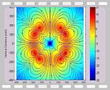
So here is an image of the 3D field strength (in dB Re: Tesla) and the in-plane field streamlines for a WB-7 grid system. Note that I am including all 3 field components (x,y,z) in the field strength calculation, but the streamlines do not show out-of-plane components. The 2D analysis plane rotates around the z-axis over time from 0 to 90 degrees. The angle at any point in the avi is shown in the title.
Unlike the previous (static) images, I am modeling each grid as a single thin loop.
The "funny" cusp shows up at 45 degrees. At about 33 degrees, the grid swings through the analysis plane.
Hopefully, this time I didn't screw up the loop currents and/or fields ...
Last edited by kbaugh on Mon Mar 15, 2010 12:06 am, edited 1 time in total.
I wish the video was slower. But, this is the best I've seen yet for the fields. Good job. When you compare this against actual photos, it does seem to play well. You can mentally tranpose the spikey ball. Now if we could include the plasma effects on the magnetic field...
When you project it in your mind, it really does show the potential for a Dodec Magrid proving a much more uniform field and improved electron confinement.
How hard would it be for you to turn this into a Dodec Model?
Actually, I was going to do one more thing with the WB-7 class grid, and then try a dodecahedron.
One thing that I did to get the avi working was to go from explicit descriptions of each field in terms of location in absolute space to a description in terms of each loops magnetic moment (unit vector in the direction of the on-axis B-field and scale parameter). That should allow me to go to any arbitrary configuration of grids as long as I know how each face is oriented and the loop radius.
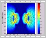
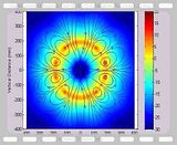
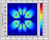
Here is another avi. As before, it shows the in-plane streamlines as the 2D analysis plane rotates around a vertical axis. In this plot, the background color indicates the strength of the out-of-plane component of the B-field in dB re: 1 Tesla. Note that the out-of-plane field strength drops to zero at 0, 45 and 90 degrees, but that there are orientations where there is a significant out-of-plane B-field. In particular, the out-of-plane field shows a fairly sharp gradient just inside the grid system at a few presentations.
DeltaV: Yes, this is MATLAB on a Windows box. I will look at what other video formats are available; "avi" was easiest. I am also looking into whether I can get the "streamslice" and "pcolor" functions in Octave.
KitemanSA: I never quite understood the rationale behind Indrek's superconducting sphere as a stand-in for a plasma swarm in the middle of the grid. I can understand modeling the plasma as a perfect electrical conductor (PEC), so that the electric fields are constrained, but I couldn't wrap my head around why it would also behave as a perfect magnetic conductor (PMC). Maybe someone with a better grasp of plasma theory could help.
Ladajo: Not sure about your question. As seen in my earlier (i.e. screwed up) versions, the streamlines will show something like a monopole in certain situations, but ultimately I am just modeling each loop using the exact analytic solution given by the complete elliptical integrals of first and second kind. I suspect that means that a true monopole won't be formed unless I screw up the model again (sigh).
I was thinking if you could figure a way to insert a monpole in the center and vary the strength, that could represent the plamsa ball. The issue I see with the PEC/PMC is representative field structure in the 3D. Maybe I am thinking about it too hard... I keep seeing it as a spherical torus.
How about a mini dodec in the center to represent the plasma?
But the plasma doesn't behave like a monopole. I thought we'd determined that way back at the beginning of the thread, when he actually had a monopole in the centre by accident...
The reason the plasma is diamagnetic has to do with the fact that it is free to develop surface/sheath currents that oppose externally-applied magnetic fields. An individual electron might not interact with the magnetic field much as a fraction of the time it spends in the wiffleball, but during those moments when it does (the turn-around at the edge) it helps produce a counter-field.
I agree, I am merely thinking of ways to simulate the effect of the plasma within the confines of the modeling software/method. The sum of the electron sheath interactions simulates a field that counters the Magrid field.
This is not a PIC sim, so we look for a method to represent the sum effect.
Dude, the plasma does not behave like a monopole, in bulk or on average or to a first-order approximation or anything. Take a look at the first post in the thread. Does that look like a wiffleball to you?
Mirror coils are probably a good start. A monopole is completely different, and is not a good start.
I think I understand a bit better now: the plasma ball at the center will behave as a diamagnetic surface. Although not spherical, it can be approximately modeled as a sphere using Kelvin's method of images. The monopole approach is easy to implement (I just add a radial component everywhere), but probably doesn't refelect the internal physics. Out of personal curiosity, I will model both and post up the results.