A question about higher order polyhedra.

Discuss the technical details of an "open source" community-driven design of a polywell reactor.

Moderators: tonybarry, MSimon

KitemanSA
Posts: 6179
Joined: Sun Sep 28, 2008 3:05 pm
Location: OlyPen WA

Re: corner coils

Post by KitemanSA »

VernonNemitz wrote: To KitemanSA, one reason I've mentioned an octahedron more than once, for the facet coils, is because there are 4 facets at each corner instead of 3. That means a round corner coil is a better shape for an octahedron corner than any other polyhedron for a Polywell (except the icosahedron which has five facets connecting at each corner).
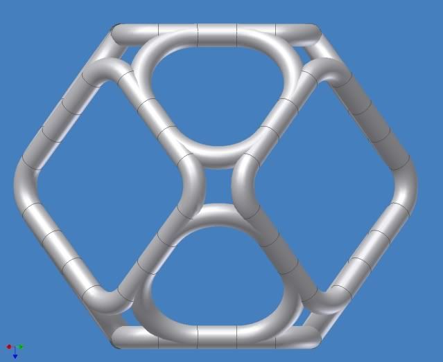
True that the truncated facet would be square, but the main facets are then triangular. Win some, lose some.
Regarding weak spots in the overall magnetic field, I'm pretty sure it is well established that the weak spots are the centers of the facets and the corners. So, if the facets have appropriately strong magnet coils, and the corners are enhanced with real coils, then any place not covered (the nubbin zone, for example) doesn't really matter; that place was not a weak spot in the first place, and will not become weak just because we added extra magnetism.
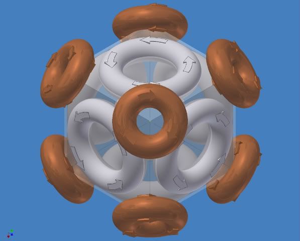
In the WB7 there are three sets of "weak spots", none of which are actually weak fields but very strong fields. They just have very little transverse (tangential) field component. The very strong fields are all radial. Since what confines is the tangential component, the cusps are holes in the confinement, not necessarily in the field.
The three sets are, the real point cusps at the center of the faces, the virtual point cusps at the center of the virtual magnets that are the facets, and the line-like cusps where the nubbins are. At leat one source has suggested that the line-like cusps dominate the loss factor. At least one other suggests that they don't. Ah, my kingdom for some data!!!!

VernonNemitz
Posts: 23
Joined: Thu May 28, 2009 3:18 pm

Post by VernonNemitz »

Hmmmm...Bussard claimed outright in his Google presentation that "the physics is done". I take that to mean the problems are solve-able, and that possibly some things that some people think are problems actually aren't (the nubbin zones, for example).

KitemanSA
Posts: 6179
Joined: Sun Sep 28, 2008 3:05 pm
Location: OlyPen WA

Post by KitemanSA »

VernonNemitz wrote:Hmmmm...Bussard claimed outright in his Google presentation that "the physics is done". I take that to mean the problems are solve-able, and that possibly some things that some people think are problems actually aren't (the nubbin zones, for example).
Well, "the physics" may be "done" but "the devil is in the details" and even DrB wasn't sure about the details. He wanted to do two more small scale models, on with "square" plan-form magnets in a cuboctahedron configuration, and another with a higher order polyhedron. Most people take that to mean some form of truncated dodecahedron. from his desire to test the rectified (fully truncated) cube, aka the cuboctahedron. I suspect he also wanted the higher order polyhedron to be a rectified dodec, aka an icosadodecahedron.

MSimon
Posts: 14335
Joined: Mon Jul 16, 2007 7:37 pm
Location: Rockford, Illinois
Contact:

Post by MSimon »

I'd go dodec - fewer coils. For the same reason a cube makes more sense than an octa. But you know - I'm prejudiced.
Engineering is the art of making what you want from what you can get at a profit.

KitemanSA
Posts: 6179
Joined: Sun Sep 28, 2008 3:05 pm
Location: OlyPen WA

Post by KitemanSA »

MSimon wrote:I'd go dodec - fewer coils. For the same reason a cube makes more sense than an octa. But you know - I'm prejudiced.
Using 12 pentagonal magnets connected at the corners produces the icosadodecahedron. Using the six "square" planform magnets connected at the corners produces the cuboctahedron. The "fewer" magnets you so dearly desire.

If fewer is so much better to you, maybe you sholuld support the triangular planform, real-virtual octahedron configuration. That only has 4 magnets!

tombo
Posts: 334
Joined: Fri May 09, 2008 1:10 am
Location: Washington USA

Post by tombo »

This was discussed some months back.

Image
-Tom Boydston-
"If we knew what we were doing, it wouldn’t be called research, would it?" ~Albert Einstein

MSimon
Posts: 14335
Joined: Mon Jul 16, 2007 7:37 pm
Location: Rockford, Illinois
Contact:

Post by MSimon »

tombo wrote:This was discussed some months back.

Image
Aligning cusps with cusps doesn't seem worth the effort.
Engineering is the art of making what you want from what you can get at a profit.

icarus
Posts: 819
Joined: Mon Jul 07, 2008 12:48 am

Post by icarus »

Ever get the feeling we are sitting between the cusps of monumental change and upheaval?

krenshala
Posts: 914
Joined: Wed Jul 16, 2008 4:20 pm
Location: Austin, TX, NorAm, Sol III

Post by krenshala »

icarus wrote:Ever get the feeling we are sitting between the cusps of monumental change and upheaval?
But is it a normal or a "funny" cusp? :)

VernonNemitz
Posts: 23
Joined: Thu May 28, 2009 3:18 pm

snaking

Post by VernonNemitz »

To MSimon, Thanks! Excellent image!

The next notion to dissect involves pretending all those coils are merged.

Open up a single existing torus and you see one wire in there wrapped many times, filling the torus.

In a merged design, that one wire snakes around all the toruses. If some distortion occurs to enable that, consider it part of this design. And, in the case of the image referenced above, I'm talking about 14 toruses, not 6.

Imagine the wire starting at a nubbin. It makes one complete loop in one torus and then crosses to another torus and loops in it, then it crosses to another and loops in it, and so on. It may be necessary to actually do a loop-and-a-fraction, to ensure all 14 toruses are included. Then repeat until all the toruses are full of wire.

Think of this design as the ultimate version of a magnetic-mirror "baseball" magnet:
http://www.pnas.org/content/68/8/1931.full.pdf
see the sketch in the upper right corner of Page 2 of that document.
Last edited by VernonNemitz on Thu Jun 18, 2009 8:48 pm, edited 1 time in total.

MSimon
Posts: 14335
Joined: Mon Jul 16, 2007 7:37 pm
Location: Rockford, Illinois
Contact:

Re: snaking

Post by MSimon »

VernonNemitz wrote:To MSimon, Thanks! Excellent image!

The next notion to dissect involves pretending all those coils are merged.

Open up a single existing torus and you see one wire in there wrapped many times, filling the torus.

In a merged design, that one wire snakes around all the toruses. If some distortion occurs to enable that, consider it part of this design. And, in the case of the image referenced above, I'm talking about 14 toruses, not 6.

Imagine the wire starting at a nubbing. It makes one complete loop in one torus and then crosses to another torus and loops in it, then it crosses to another and loops in it, and so on. It may be necessary to actually do a loop-and-a-fraction, to ensure all 14 toruses are included. Then repeat until all the toruses are full of wire.

Think of this design as the ultimate version of a magnetic-mirror "baseball" magnet:
http://www.pnas.org/content/68/8/1931.full.pdf
see the sketch in the upper right corner of Page 2 of that document.
Complicated winding schemes reduce fill fraction.
Engineering is the art of making what you want from what you can get at a profit.

VernonNemitz
Posts: 23
Joined: Thu May 28, 2009 3:18 pm

Re: snaking

Post by VernonNemitz »

MSimon wrote:Complicated winding schemes reduce fill fraction.
True, but not necessarily unmanageably so. For example, the crossover places could be bigger than the general minor-diameter of each torus. Ideally, each loop-and-a-fraction would be multiplied such that a whole number of loops resulted, in each torus. Net result is, every torus is completely filled. That's the major design challenge here, to work out a winding scheme that accomplishes that.

The main purpose of this is to ensure EVERY place where the magnetic field passes through the "shell" of connected toruses...every place is the center of a torus (or distorted torus).

MSimon
Posts: 14335
Joined: Mon Jul 16, 2007 7:37 pm
Location: Rockford, Illinois
Contact:

Re: snaking

Post by MSimon »

VernonNemitz wrote:
MSimon wrote:Complicated winding schemes reduce fill fraction.
True, but not necessarily unmanageably so. For example, the crossover places could be bigger than the general minor-diameter of each torus. Ideally, each loop-and-a-fraction would be multiplied such that a whole number of loops resulted, in each torus. Net result is, every torus is completely filled. That's the major design challenge here, to work out a winding scheme that accomplishes that.

The main purpose of this is to ensure EVERY place where the magnetic field passes through the "shell" of connected toruses...every place is the center of a torus (or distorted torus).
And all that assumes the magnetic field is workable and you can do it with superconducting wires. Keeping the wires immobile and properly insulated.
Engineering is the art of making what you want from what you can get at a profit.

KitemanSA
Posts: 6179
Joined: Sun Sep 28, 2008 3:05 pm
Location: OlyPen WA

Re: snaking

Post by KitemanSA »

VernonNemitz wrote:To MSimon, Thanks! Excellent image!

The next notion to dissect involves pretending all those coils are merged.
Actually, it was tombo's image. And here is another of tombo's images that has the coils merged as you suggest. This one has the main coils square like DrB wanted with real tringular magnets like you and a number of others have suggested.

Image

VernonNemitz
Posts: 23
Joined: Thu May 28, 2009 3:18 pm

image

Post by VernonNemitz »

I apologize to tombo for not paying close attention (went to bottom of postings and scrolled up to see image, and then neglected to notice it was a quoted reply).

The merged-coil image is "off" in a few ways from my mental image, which is OK since that image preceded my posting by who-know-how-long.

First, I haven't been pushing for deliberately distorted coils (triangular and square); I was just expecting some distortion would be necessary to do what I was imagining.

Second, there should be exactly 14 holes; that image has the 6 main torus hole, 8 corner torus holes, plus a lot of extra holes because the torus merging isn't as complete as I was imagining.

Third, the places where the coils are merged aren't fat enough. They need to accommodate the fact that if each torus is full of wire, then the merge locations need to have at least 1.414... times the diameter of the regular minor-diameter of each torus (some places may need to be even thicker).

Post Reply