All here
http://www.mare.ee/indrek/ephi/icarus1/
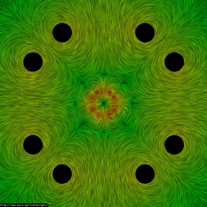
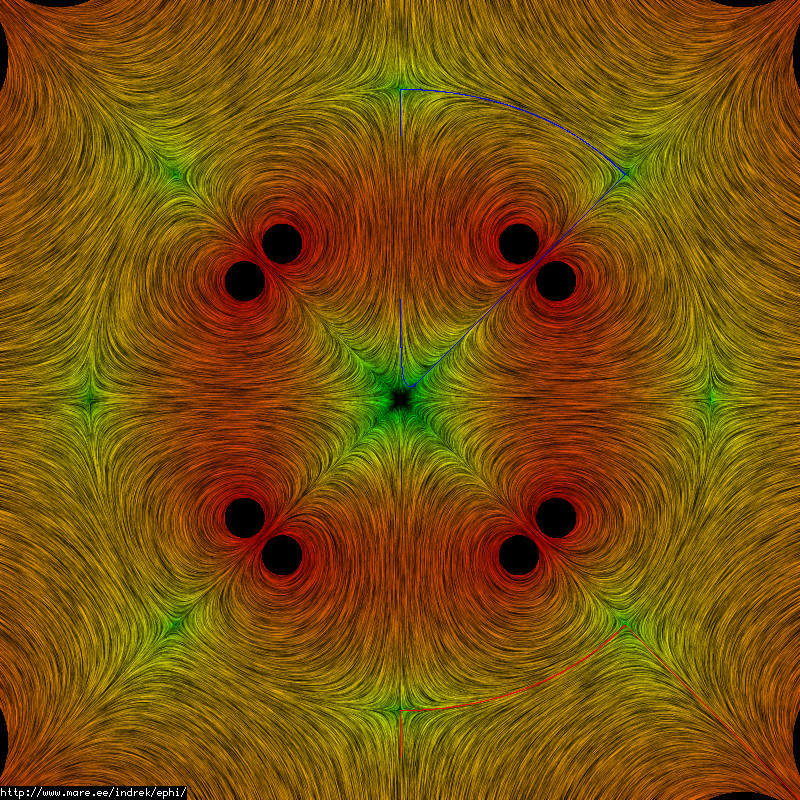
Unless there's some oversight here, this concavity would have to be compensated for by recirculation or some other mechanism... you can't be convex at all points. It would have to be a perfect sphere or some mix of convex and concave surfaces.tombo wrote:Nice Work!
That surface looks concave toward the plasma.
Do these results mean that the polywell is unstable at those points?
In 2-d yes, in the 3D most likely but exactly how, well that is one of the great open questions for mathematical physics I think. How do you relate a 3-d curl to a twisted, curved streamsurface?I was under the impression that the gradient and the curvature were intimately related.
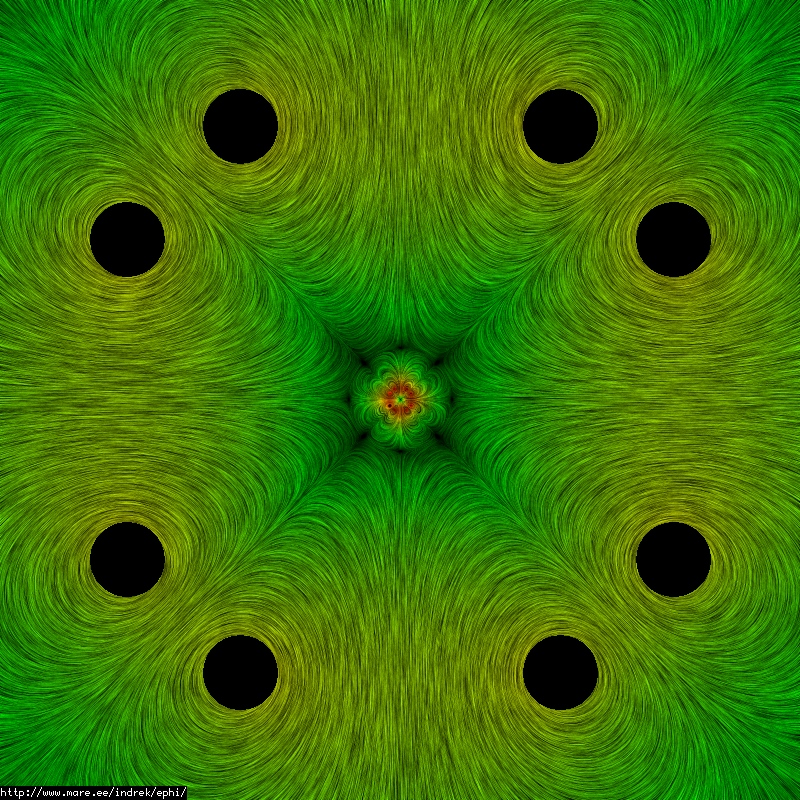
Pertaining to the field strength gradient criteria, just maybe. Thinking out loud, I think when the wiffle-ball will fail will be when the surface starts to pinch up into plasma droplets at the cusps and leak out there, a full blown failure it will be blasting out the cusps. Google "G.I. Taylor's four-roller experiment" for analogous 2-d cylindrical flows trapped in cusps and instability regimes for some more ideas, particularly relevant if there was identified a physical source for an analogous effect to surface tension between the interior and exterior. Then it would become a balance between magnetic pressure, plasma pressure, volume of ball and interfacial "tension".So, you think that this picture shows a stable well?
To some extent I think if it is stable and somewhere near these stationary solutions the "plasma" interior solution to the first-order will match continuity and field direction across the wiffle-ball surface. It is not superconducting or inviscid but those approximations are a good place to begin, in my opinion. Down in the very interior who knows, particularly with the electrostatics coming heavily into it.Does you model also predict that the virtual coil currents are real plasma currents?
(perhaps actually spread out more than the idealized concentrated currents?)
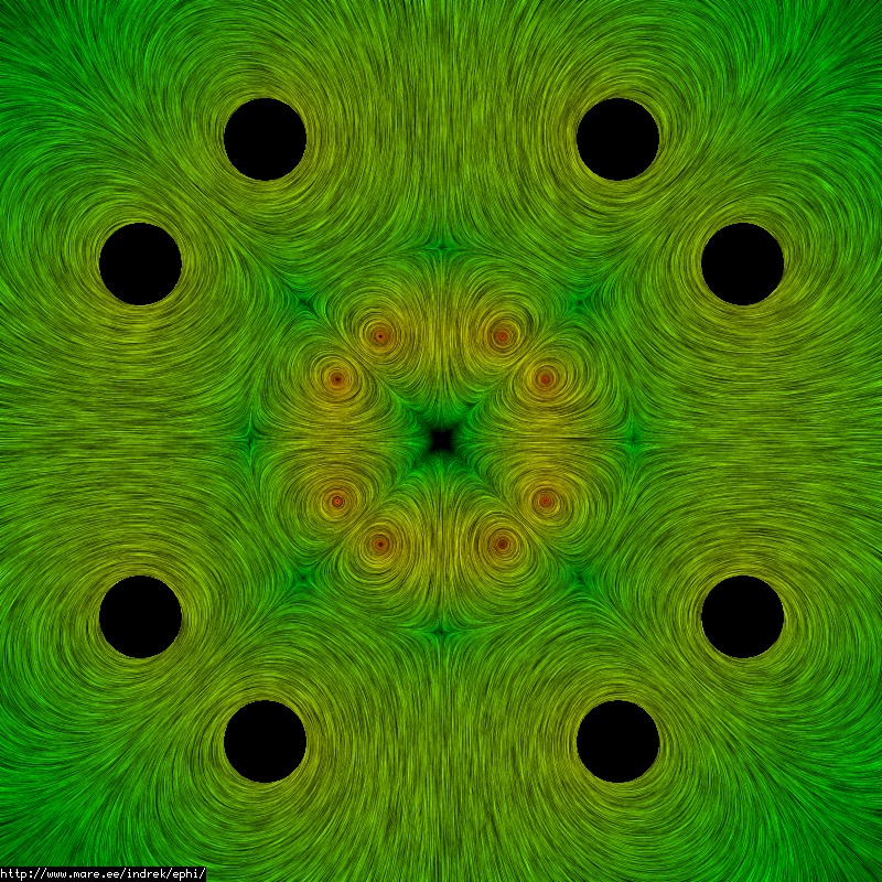
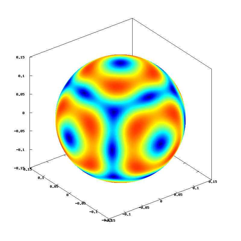
How much of the detail inside of the sphere do you think represents real fields?
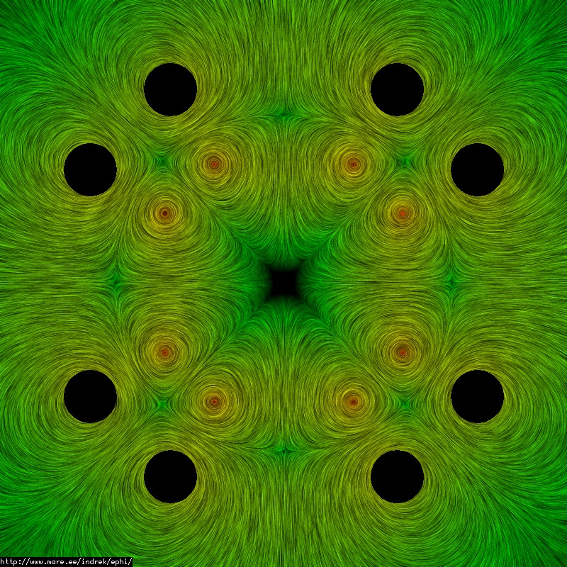
I think you have to tune the spacing between the inner coils so that the field lines don't terminate inside. I tried this manually here:kcdodd wrote: I decided to attempt this as well just guess the value should solve for the sphere radius. ...
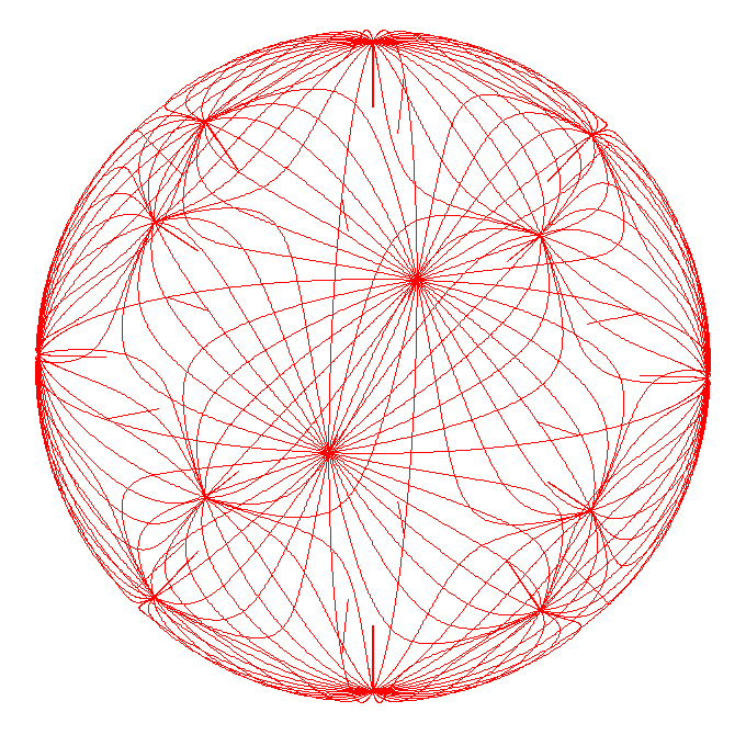