Good. Thank You.
The shape of the virtual coils in any configuration with circular toroidal coils is a funny concave shape that I see as a problem.
Now as I see it, the confinement of any individual mirror is independent of the field direction (in or out).
So combine this with the MPG concept.
I would like to propose a Magrid configuration:
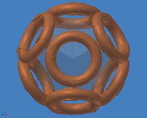
Consider the octahedral configuration.
It is the simplest polyhedron that meets the patent requirements.
This configuration has half as many poles as the truncated octahedron=truncated cube.
But the field lines are still everywhere convex toward the plasma.
This configuration meets the patent geometry requirements with an even number of faces around each vertex and an in-out-in-out field orientation.
Advantages over cube or dodecahedron with toroidal coils:
The field lines naturally conform to all the material surfaces.
This configuration does away with the funny cusps since all the faces are the same.
There are no concave coils or virtual coils.
Note the Eulerian path.
The field lines vary smoothly from point to point everywhere.
There are no null fields as the field reverses direction only at coils.
There is no need for electrical connections between coils within the vacuum chamber.
The feed lines are shielded by the full current of the Magrid.
Coolant can flow smoothly through the whole coil assembly.
There is no need for coolant joints inside the vacuum chamber.
The coil could be full of wires connected outside the chamber to form a coil, but I prefer to make it in one coil made of copper tubing with coolant flowing through it.
The points where the adjacent loops come near each other have the sharpest bends and the closest spacing so the highest fields occur exactly where mechanical ties might be needed. I’m thinking quartz fiber ties.
The field would be even higher at that spot than for a set of round coils (WB6, WB7) because of the smaller local radius. Ie. It looks like a smaller coil of the same current from up close.
This geometry can be fabricated in a straightforward manner.
The tubes can possibly be thick enough to be free standing.
I have experience using water cooled copper tubing as power conductors in RF induction furnaces.
The technology is tried and true. It works very well, so well that one of the problems was condensation from too much cooling.
I prefer the one turn configuration because:
The field is due to the amp-turns so 200 turns at 1000 amps (WB6) makes the same field as one turn at 200,000 amps.
The resistance losses are the same too, because power loss goes up as the square of the current and the resistance goes down as the square of the wire radius.
So trading turns for current is a wash for resistance losses as long as the total conductive cross section is the same.
One turn is better for keeping the field lines conformed to the material surfaces.
One turn is better because there are no packing factor losses and no insulation taking up space or failing.
One turn is worse for feed line losses. But, this is balanced by the magnetic shielding of the feed lines.
Also, these resistance considerations go away when we get to superconductors.
One turn gives less complexity inside the chamber and more complexity outside the chamber in the form of a higher current power supply.
A good EE should have no problem solving that.

(I really wanted to use a tongue-in-cheek but it isn’t available)
Moving the complexity to the outside of the vacuum chamber counts as a good move in my book.
I think a low duty cycle experimental device with simple water cooled standard sized copper tubing could prove the configuration and prove the Polywell concept.
It would recover between shots very quickly.
Also, it would be easy to make.
I have built much more complicated bent-tube piping systems.
I think the MPG’s were on the right track. They worked well and even made DD fusions.
They just needed much more current.
But wait it gets better:
Consider:
This configuration can move 4 times a much heat out of the chamber.
It also is mechanically stronger and more stable.
The parts are very simple and easy to make.
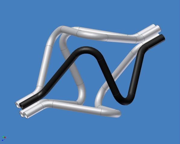
Also note the quadrupole between the feed lines.
That looks like a null B field along that line.
It could be a particle escape path. But it should not be too bad because it is so long compared to its width.
But in addition to an escape path I think it could be a path along which to carefully aim an electron gun and an ion gun for particle injection.
The feed lines should be configured and spaced to coordinate with the injection guns, to create impedance matched RF feed lines (for POPS mode) and to place them in the coil’s particle & radiation shadow.
Question for the particle gun guys and the RF guys:
Does it really work this way or am I barking up the wrong tree?
I will make shop drawings if anyone has the resources to build it.
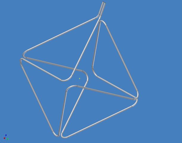
It even seems to work if we need to build up the conductors to 8” diameter to accommodate many layers of insulation and various temperature cooling passages.
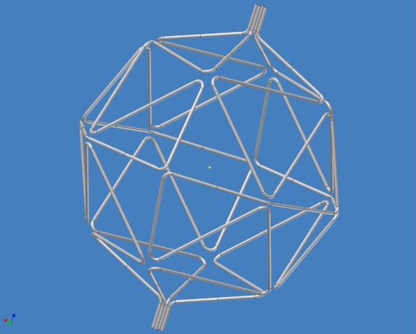
Here is what it looks like for a 2 meter diameter Polywell with 8 inch thick coils.
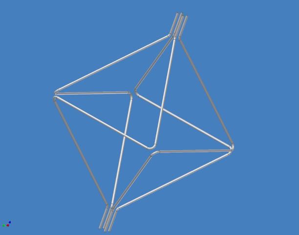
OK. Now if that works and if we don’t need 8” thick pipes, here is a further refinement:
Same showing only 1 of the 4 circuits:
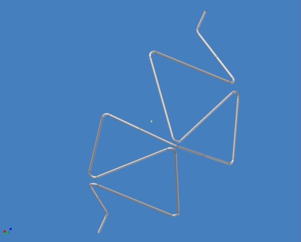
This shows the octahedron modified to add a triangular loop inside each triangular coil making it a 32-hedron. (I call it an 8x4-hedron.)
It breaks each of the octahedron’s triangular faces into 4 triangular faces.
The fields in adjacent faces are still alternating and smooth and convex toward the plasma inside with no null fields, except between the feed lines.
It makes the device closer to a sphere, which I intuitively think is a good thing.
Here are some rationalizations for 32 faces being better than 8 faces:
1. The 32 face configuration reduces the current by a factor of 4 to create the same magnetic field. (This assumes that a triangular coil scales like a circular coil.)
2. It has a smoother field.
3. The same reasons that WB7 is a dodecahedron rather than a cube.
4. There is a larger volume of low field in the center creating larger well volume.
Is this true and is it actually a good thing?
5. There is less mechanical force on the coils.
The forces parallel to the surface of the sphere cancel out and the only total force on a segment is a radial force which is a fraction of the total force so each segment of tube does not need to be as strong.
This advantage does not apply to the coil ties. The ties being parallel to the sphere surface see the full force.
The ties are not shown but might need to be installed at some or all of the sharp bends to resist the mechanical forces trying to expand the sphere.
6. The water flow volume even through this many bends is still sufficient to carry away a prodigious amount of heat, especially if the flow rate is pushed high enough to shorten part life with erosion pitting etc.
(I don’t believe my own numbers so I won’t say them. I need a second opinion here.)
But, for an empirical anchor: At 46 minutes into the Google video the MPG’s show about ¼” diameter tubes & Dr Bussard says they were limited by steam to 2kAmp.
Going from 1/4” tube to 1” tube decreases the resistance by factor of 8, increases flow cross section by a factor of 23. Assuming their flow speed I get a total increase of 188 times to a total of 377kA, which is well beyond the 200kA preliminary target.
This is all for standard wall tubing.
If we go to thicker wall and OFHC copper the cooling load will decrease.
Also, I have fewer bends in each circuit to restrict water flow than MPG-1.
Also, the larger tube will have a smaller friction coefficient.
So I am in the ballpark.
I need to work on my water flow model. It is not quite right.
Also I need to calculate the heat flow through the bulk copper and across the interface into the coolant.
But, in any case it should be good enough for a sufficiently low shot rate in the experimental model.
The next refinement is to add yet another triangular coil inside each triangular coil:
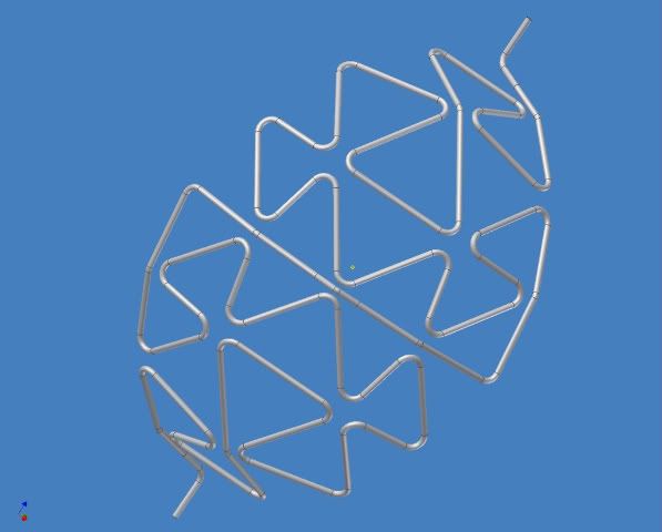
I show only one quarter of it to reduce visual clutter.
This is even closer to a sphere and increases the advantages above.
This process can be extended indefinitely to make 128-gons, 512-gons, 2048-gons etc.
It is similar to a Sierpinski triangle. But, it is harder to make because all the triangles of a given size need to be filled in.
We have to stop somewhere due to increased coolant flow resistance.
If needed, we could increase the number of circuits to 8 or more to mitigate this but at some point complexity overwhelms us.
These parts could be mass produced on a 4-slide machine.
In fact, I think that if they were simple copper tubes they would be cheap enough to be consumable parts.
Further Refinements:
I think the outside of the tube needs a plating to reduce out-gassing and to enhance thermal reflectivity.
Perhaps that would be bright-nickel, chromium, gold or boron (for neutrons and heat).
I think it might be possible to deposit a superconductor on the inside of the tube using electroplating, thermal deposition or CVD after fabrication.
But this is whole new problem of its own that could easily become a distraction from this effort. Probably worth a PhD to someone though if they can do it and widely applicable.
I’m pretty sure Hyper Tech Research's CTFF process could be modified to incorporate a coolant tube down the centerline of the superconducting wire.
I also have many further details in mind but the basic concept must work first.
Concerns:
1. What does the field look like inside a triangular turn?
Specifically what is the minimum field at the center? I can’t solve it. I’ve done all my calculations based on assuming it to be like a circular coil of the same size.
2. What does the field look like between turns where they come close together?
More to the point what is the particle flux in this vicinity where the mechanical ties would need to be?
3. How well do the field lines conform to the tube in the vicinity of the sharp bends?
4. How is the overall field shaped?
5. How does the electron recirculation work with this field shape?
5. a) Is it a problem having the opposite faces with different polarities as long as the field is everywhere convex toward the plasma?
5. b) Is it better to have the field line arches penetrate deeply into the center creating a gradient further into the well or is it better to have them stay closer to the magrid sphere leaving a larger flatter well? This affects the choice of the number of faces.
6. Some triangles are equilateral and some are 45-90.
This difference may be a problem. If it is, the problem might be reduced by equalizing the triangle areas.
But I think it will be less of a problem than the in-bending triangles of the virtual coils at the cube corners of a standard PW.
7. Thermal issues need to be fleshed out.
8. Mechanical stress details need to be fleshed out.
9. Chamber wall feed-throughs need to sorted out.
10. The field and plasma modeling are beyond me.
11. The usual problems. I.e. all the things that I did not see coming.
Thank you for reading this far.
I’m hoping that some of you will find this design intriguing enough to give it serious consideration.
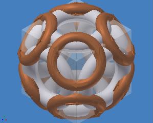
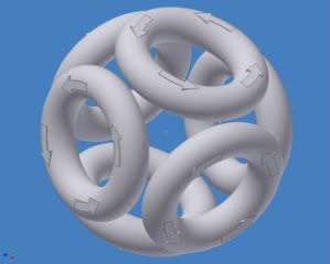 Here is the virtual coil shown overlaid on it:
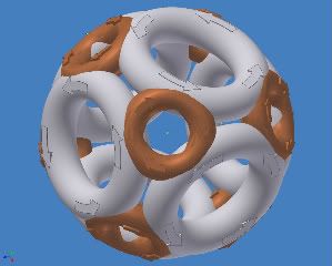
 Or finally this: