Kiteman is adding complexifying jargon and mixing terminology unnecessarily. The confluence of the line cusps at the corners is just simply that ... it is not a corner cusp, funny cusp or a point cusp.
Technically speaking, for each simple closed curve of a magnet coil there is only one point cusp, in the center, and a surrounding line cusp around the boundary of the mag-field enclosing that magnet. You've been warned.
magrid configuration brainstorming
I have not invented any jargon except "X-Cusp" which I aknowledged repeatedly. "Funny"" and "line-like" I got from Dr. B. "Corner" is Dan's, I think. I don't personally believe there IS such thing as a "corner" cusp, but I don't pretend to be infinitely knowing. As I told Dan, what he is calling a corner cusp is merely a point cusp in WB6 like machines or line cusps in yours.icarus wrote: Kiteman is adding complexifying jargon and mixing terminology unnecessarily. The confluence of the line cusps at the corners is just simply that ... it is not a corner cusp, funny cusp or a point cusp.
Where do I ever have a point cusp except at the center of a real or virtual magnet? Never. Please don't ascribe to me your mis-understandings.icarus wrote:Technically speaking, for each simple closed curve of a magnet coil there is only one point cusp, in the center, and a surrounding line cusp around the boundary of the mag-field enclosing that magnet.
Ooooo, I'm terrified. As I stated elsewhere, if you can't do anything but snipe, please go away.icarus wrote:You've been warned.
That is indeed my understanding of the imaginary funny cusps that Bussard referenced. I say immaginary as in that model the magnets were described mathmatically as infinitly thin lines with infinitly small space between them, so the cusp area was essentially zero, irregardless of it's lenght. In this case the corner cusp (the triangular area) could be considered as somewhat point like as there was zero width line cusps running out of that area. But once the spacing of WB6 was introduced due to the realization of the need for several gyroradii separation of real magnets, this is no longer the case. To speak of funny cusps is a confusing compromise. And to speak of these corner cusps as point cusps is also inappropriate, as the cusps running into the region of what was referred to as the funny cusps now always have some finite width. In a sense, the corners are all connected to each other with a continous uninterupted branching line cusp. The losses through this cusp is worse than the conceptual model, but that is OK as recirculation more than makes up the difference. And any compromise in the Wiffleball traping factor is apparently tolorable. In WB6, and WB7 what was conceptually pictured as funny cusps was replaced by interconnects/ nubs. These served to isolate the various corners somewhat, but only at the cost of unshielded surfaces increasing losses . In other configurations of a magrid where the individual magnet coilds are supported on standoffs from the wall, even this flawed segragation of the cornera that would allow them to act somewhat as flaky point cusps becomes less tenable.KitemanSA wrote:You know, I don't really know the morphology of a funny cusp except that it has been describes as a point of zero field with zero radius.happyjack27 wrote:my understanding is that a "funny cusp" refers to what i would call a "saddle cusp" because it looks like [url=http://en.wikipedia.org/wiki/Saddle_point]this[url]. so there are three cusp types: point (roughly z=x^2+y^2), line (roughly z=x^2, y = 0) a, and saddle (aka "funny") (roughly z=x^2-y^2). those represent all of the morphologically distinct possibilities for "cusps" in 3 dimensions.
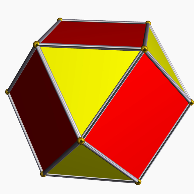
Imagine a WB that looked like this cuboctahedron. The red faces are square magnet coils (silver bars) of zero minor radius with the same polarity pointed inward. The yellow triangles would be virtual magnets with that polarity pointed OUT. Every vertex (gold balls) on that figure would be a funny cusp. In the middle of each face would be a point cusp. THAT IS IT for a "true" polywell. But magnets can't be made with zero minor radius and WB6 proved that the coils shouldn't touch so the closest we can get to this figure is the one I posted about two posts back.
All of this is of course word play. The only thing that counts is the containment efficiency of these areas, and just as important (or more so) is how compatable they are with recirculation.
Admittedly, thoug, it would be convient to have a consistant terminology.
Oh, and by the way, where does the requirement for four opposing magnetic fields surrounding a cusp come into play? In some designs there are 4 (like my bowed 4 grid design). But, I can count only two or three in any area of WB6 that come into play.
Dan Tibbets
To error is human... and I'm very human.
That is indeed my understanding of the imaginary funny cusps that Bussard referenced. I say imaginary as in that model the magnets were described mathematically as infinitely thin lines with infinitely small space between them, so the cusp area was essentially zero, irregardless of it's length. In this case the corner cusp (the triangular area) could be considered as somewhat point like as there was zero width line cusps running out of that area. But once the spacing of WB6 was introduced due to the realization of the need for several gyroradii separation of real magnets, this is no longer the case. To speak of funny cusps is a confusing compromise. And to speak of these corner cusps as point cusps is also inappropriate, as the cusps running into the region of what was referred to as the funny cusps now always have some finite width. In a sense, the corners are all connected to each other with a continuous uninterrupted branching line cusp. The losses through this complex cusp is worse than the conceptual model, but that is OK as recirculation more than makes up the difference. And any compromise in the Wiffleball traping factor is apparently tolorable. In WB6, and WB7 what was conceptually pictured as funny cusps was replaced by interconnects/ nubs. These served to isolate the various corners somewhat, but only at the cost of unshielded surfaces increasing losses . In other configurations of a magrid where the individual magnet coils are supported on standoffs from the wall, even this flawed segregation of the corners that would allow them to act like (or be described as) somewhat flaky point cusps becomes less tenable.KitemanSA wrote:You know, I don't really know the morphology of a funny cusp except that it has been describes as a point of zero field with zero radius.happyjack27 wrote:my understanding is that a "funny cusp" refers to what i would call a "saddle cusp" because it looks like [url=http://en.wikipedia.org/wiki/Saddle_point]this[url]. so there are three cusp types: point (roughly z=x^2+y^2), line (roughly z=x^2, y = 0) a, and saddle (aka "funny") (roughly z=x^2-y^2). those represent all of the morphologically distinct possibilities for "cusps" in 3 dimensions.
Imagine a WB that looked like this cuboctahedron. The red faces are square magnet coils (silver bars) of zero minor radius with the same polarity pointed inward. The yellow triangles would be virtual magnets with that polarity pointed OUT. Every vertex (gold balls) on that figure would be a funny cusp. In the middle of each face would be a point cusp. THAT IS IT for a "true" polywell. But magnets can't be made with zero minor radius and WB6 proved that the coils shouldn't touch so the closest we can get to this figure is the one I posted about two posts back.
All of this is of course word play. The only thing that counts is the containment efficiency of these areas, and just as important (or more so) is how compatable they are with recirculation.
Admittedly, though, it would be convenient to have a consistent terminology.
Oh, and by the way, where does the requirement for four opposing magnetic fields surrounding a cusp come into play? In some designs there are 4 (like my bowed 4 grid design). But, I can count only two or three in any area of WB6 that come into play.
Dan Tibbets
To error is human... and I'm very human.
In the case of Dr. B's polywell, the cusp had zero length also. A point of zero field with zero radius is how someone described it long ago. I don't remember who, maybe even Dr. B.D Tibbets wrote: That is indeed my understanding of the imaginary funny cusps that Bussard referenced. I say immaginary as in that model the magnets were described mathmatically as infinitly thin lines with infinitly small space between them, so the cusp area was essentially zero, irregardless of it's lenght.
What you call a "corner cusp" is what others call the "out" magnet, assuming the red is the "in". And since his patented polywell touched at all the verticies, they wouldn't have been virtual. They became virtual with the WB6, but none-the-less the field acts as if there is a real magnet except in the very corners.D Tibbets wrote: In this case the corner cusp (the triangular area) could be considered as somewhat point like as there was zero width line cusps running out of that area.
With the WB6 round magnet design, the point where the funny cusp would have been in his patented design was replaced by line-like cusps; his term. What he wanted to do per the Valencia Paper was to replace the round coils with "square plan form" magnets. This would have made those locations shorter line like cusps, approaching a funny cusp configuration.D Tibbets wrote: But once the spacing of WB6 was introduced due to the realization of the need for several gyroradii separation of real magnets, this is no longer the case. To speak of funny cusps is a confusing compromise.
I don't speak of thiose locations as point cusps. The center of the triangulare area has a point cusp. The locations where the square plan form magnets come closest become shorter line-like cusps approaching funny cusp conditions.D Tibbets wrote: And to speak of these corner cusps as point cusps is also inappropriate, as the cusps running into the region of what was referred to as the funny cusps now always have some finite width.
With the round planform magnets of WB6, that is almost the case, though in my opinion the KCDodd bag analysis shows them petering out before the point cusp forms. With a square plan form magnet, they would peter out much more fully and the point cusp at the center to the more truly triangular field would be a stronger point.D Tibbets wrote: In a sense, the corners are all connected to each other with a continous uninterupted branching line cusp.
"This"? Be more specific please.D Tibbets wrote: The losses through this cusp is worse than the conceptual model, but that is OK as recirculation more than makes up the difference.
In truth, I have no idea what this last statement is trying to say. "Less tenable"?D Tibbets wrote: And any compromise in the Wiffleball traping factor is apparently tolorable. In WB6, and WB7 what was conceptually pictured as funny cusps was replaced by interconnects/ nubs. These served to isolate the various corners somewhat, but only at the cost of unshielded surfaces increasing losses. In other configurations of a magrid where the individual magnet coilds are supported on standoffs from the wall, even this flawed segragation of the cornera that would allow them to act somewhat as flaky point cusps becomes less tenable.
I do not believe Dr. B agreed with this. He stated that he wanted to try a square planform magnet, obviously believing it held some promise at improving the situation. I'd like to see his thoughts investigated.D Tibbets wrote: All of this is of course word play. The only thing that counts is the containment efficiency of these areas, and just as important (or more so) is how compatable they are with recirculation.
Perhaps you should weigh in on the FAQ.D Tibbets wrote: Admittedly, thoug, it would be convient to have a consistant terminology.
If I said four OPPOSING fields it was a slip of the digits. I try to always say "ALTERNATING" fields. In the cuboctahedron you "quoted" from my post, each and every vetex (gold ball) is surrounded by 4 alternating fields, red-yellow-red-yellow; aka square- triangular-square-triangular. That is where the statement comes from. In WB6 they were more round-convex triangular-round-convex triangular but the convexity of the triangular leads that vertex to be more of a line instead of a point which is the origin of the line-like cusp.D Tibbets wrote: Oh, and by the way, where does the requirement for four opposing magnetic fields surrounding a cusp come into play? In some designs there are 4 (like my bowed 4 grid design). But, I can count only two or three in any area of WB6 that come into play.
-
rjaypeters
- Posts: 869
- Joined: Fri Aug 20, 2010 2:04 pm
- Location: Summerville SC, USA
I've done some preliminary work on the icosidodecahedron. I'm using a sphere 1.5 m radius w/ coil diameter of 0.2 m. With parallel coil sections minimized (i.e. point the polygon corners at each other):


The close approach of the two coils is 6 cm (the magenta line).
NB: I haven't attempted to "spherize" this configuration and I won't until someone gives a coil separation distance. Anything equal to or greater than 6 cm is going to be a problem for the triangular coils.
Next victim: Cuboctahedron Edit: Never mind. I've already done it under another name.
My software wouldn't let me "pipe" the upper left fillet for some reason.
P.S. Sorry for the delay, real life intrudes on the virtual, sometimes.
Last edited by rjaypeters on Mon Nov 01, 2010 5:11 pm, edited 1 time in total.
"Aqaba! By Land!" T. E. Lawrence
R. Peters
R. Peters
What is with the little red triangle? For the "real-virtual" configuration like the WB6 all you need is the green pentagons.
Also, the sides of the pentagon should line up with the edge of the icos"i"dodec. They should run directly between the vertices but curve away before they are reached. Just a nit-pick on the way to perfection!
Great work by the way.
PS: The coils seperation is a function of the magnet strength, AFAIK, so it should be smaller with a bigger "pipe".
Last edited by KitemanSA on Mon Nov 01, 2010 8:57 pm, edited 1 time in total.
-
rjaypeters
- Posts: 869
- Joined: Fri Aug 20, 2010 2:04 pm
- Location: Summerville SC, USA
Okay, that's a LOT simpler. thanks.
Edit: Icosidecahedron ~3m diameter, 20cm diameter coil with 16cm coil close approach.
Edit: big pictures.


Note: different appearance of individual coils (not so many segments) results from finding a faster way to model.
Edit: Icosidecahedron ~3m diameter, 20cm diameter coil with 16cm coil close approach.
Edit: big pictures.
Note: different appearance of individual coils (not so many segments) results from finding a faster way to model.
Last edited by rjaypeters on Mon Nov 01, 2010 5:08 pm, edited 2 times in total.
"Aqaba! By Land!" T. E. Lawrence
R. Peters
R. Peters
Concerning Kiteman's comments on my post above. The less tenable adjective refers to the description, not the actual performance of this cusp area, whether you call it a corner, out, or virtual point cusp. It is not a "real Point cusp " or a near real point cusp, as illustrated by the relative losses. Even though the area of the corner regions are smaller with closer magnets and therefor stronger magnetic fields their losses are ~ 5-6 times greater than the point cusps (as stated in the 2008 patent application). this is tolerable because of recirculation. What the losses in these triangular regions would be with the magnets touching might be better, but because of losses to resultant unshielded surfaces the recirculation recovery would suffer and apparently the net effect is worse. This has a direct impact on the design (WB6 and WB7) there there is spacing and also unshielded surfaces (the interconects/ nubs). This would be a double whammy on the net confinement efficiency. Perhaps it emphasizes the importance of this area as a target for optimization such as shielded standoffs, or more complex forms such as that presented earlier, though I still think it has unshielded surfaces ("X cusps" in the small squares), but the rest of the "corner"/ triangular cusps would be true point cusps. The net gain may be positive.
As for the square grids rotated 45 degrees from each other, is this before or after the WB6 epiphany? Does it matter?
Dan Tibbets
As for the square grids rotated 45 degrees from each other, is this before or after the WB6 epiphany? Does it matter?
Dan Tibbets
To error is human... and I'm very human.
Dan,
Do you have reference to the 2008 patent app?
From his Valencia paper I was under the impression that the 5ish times worst applied to the line like cusp that happens in lieu of the funny cusp, not to the virtual point cusp. I'd like to read what makes you think otherwise. I'm always up for learning better!
The "squares" meeting at the corner is a direct inference from his original patent that shows the cuboctahedral polywell. If the square faces of that machine are the real magnets, they will meet corner to corner, not side to side. This has been a long term description of the polywell. The rounding of the corners is mentioned in the Valencia Paper which I deem the result of his pre-WB6 breakthrough.
OMG, and bowed too! Marvelous, simply marvelous.rjaypeters wrote:Okay, that's a LOT simpler. thanks.
Edit: Icosidecahedron ~3m diameter, 20cm diameter coil with 16cm coil close approach.
Note: different appearance of individual coils (not so many segments) results from finding a faster way to model.
-
rjaypeters
- Posts: 869
- Joined: Fri Aug 20, 2010 2:04 pm
- Location: Summerville SC, USA
A copy (with illustrations) is at :KitemanSA wrote:Dan,
Do you have reference to the 2008 patent app?
From his Valencia paper I was under the impression that the 5ish times worst applied to the line like cusp that happens in lieu of the funny cusp, not to the virtual point cusp. I'd like to read what makes you think otherwise. I'm always up for learning better!
The "squares" meeting at the corner is a direct inference from his original patent that shows the cuboctahedral polywell. If the square faces of that machine are the real magnets, they will meet corner to corner, not side to side. This has been a long term description of the polywell. The rounding of the corners is mentioned in the Valencia Paper which I deem the result of his pre-WB6 breakthrough.
http://prometheusfusionperfection.files ... tent08.pdf
Some interesting paragraphs include 88,95,97,101,102, 167,168,172, 173.
Also, page 51.
I either missed it on this rereading, or I imagined the comparison of the physical face point cusps and the triangular point "virtual" point cusps. The patent application did mention that the intercepts (where the nubs would be and what made up the original funny cusp) were of particular concern for containment. That would argue that this area does dominate over the virtual point cusp. He (Bussard?) said that the labeled point cusps had holes with a size on the order of a couple of electron gyro radii at those energies (~0.5 to 1 mm). This despite that the 'funny cusp' areas had the highest mirroring effect due to the strongest opposing magnetic fields. Perhaps the presence on unshielded surfaces in this area drove his concern.
What confuses me is how these intercept areas/ (used to be) funny cusps can be considered as separate from the virtual magnet point cusp. Is the line cusp pinched off somewhere between the intercept area and the center of the triangular virtual magnet point cusp? There is a magnetic field illustration of the WB6 configuration that shows some variation in the field strength in these areas, that might be enlightening, but I don't know how to find it.
Dan Tibbets
To error is human... and I'm very human.
-
rjaypeters
- Posts: 869
- Joined: Fri Aug 20, 2010 2:04 pm
- Location: Summerville SC, USA
