Outstanding bit of work. Useful for water cooled fusors.
For WB machines there is a big problem: the magnetic fields do not all face the same way.
magrid configuration brainstorming
Hello Simon,
I was under the (perhaps mistaken) impression that the WB series had all their magnets' North face pointing inwards; and that the return pole was a virtual magnetic face through the holes where three circles "meet". Certainly Indrek's visualisations imply this.
Please feel free to correct my understanding here.
Regards,
Tony Barry
MSimon: I think Tony's right. On the magrid, there are areas of alternating magnetic polarity: the corner cusps vs. the center cusps. Tom's 'coil' setup covers the entire surface, so there aren't really any corner cusps. Therefore, the magnetic field going 'in' through some of the 'coils' has to come 'out' through other 'coils'.
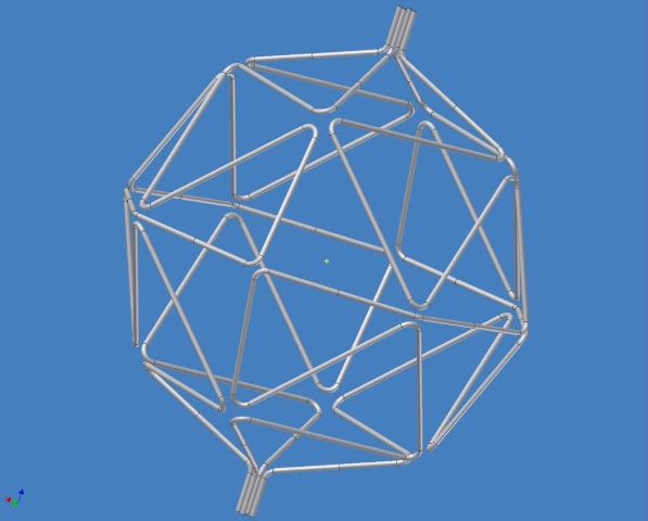
@Tombo: Now you're talking! I like the look of that.
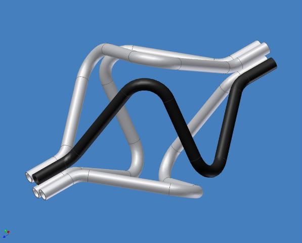
@Drmike, Indrek: how much trouble would it be to model a coil system like that? The straight segments should be quite simple, but in order to be realistic they must have a non-zero turn radius at the corners, so that'll complicate things a little bit.
@Tombo: Now you're talking! I like the look of that.
@Drmike, Indrek: how much trouble would it be to model a coil system like that? The straight segments should be quite simple, but in order to be realistic they must have a non-zero turn radius at the corners, so that'll complicate things a little bit.
Hello Tom,
I take your image here and look at it and I think I see some kind of problem.
On the regular polywell, according to Indrek's visualisation, all faces of the MaGrid point the same way (we will assume North face In). On your picture, some of the MaGrid faces point out.
If you were to stand inside the polywell while it is operating, and look out at a given MaGrid coil, then the coil current would be orbiting clockwise in every coil regardless of the direction you look.
The other half of the magnetic circuit isn't really there (it's kind of implied) because the field lines come "in" towards you through the hole in the centre of each donut, and "out" through the funny triangular hole at the corner where three rings touch.
The corollary to this is the current in a given donut is going in the opposite direction to the current in a donut that is touching it.
Now I'd be grateful if Tom Ligon or MSimon or Dr Mike could chip in here if I'm wrong.
This seems to me to be magnetic confinement - North Faces In, opposing each other, creating a region in the centre where the magnetic flux density is lowest (a well) and which climbs rapidly the closer you get to the MaGrid. When electrons are injected into this well, they orbit around the MaGrid, into the region in the centre and then out through the triangular hole and round and back in. The higher their energy, the more they "spin" along these field lines so their path is like a corkscrew rather than a straight loop.
As the magnetic field is increased in intensity, the field lines near the centre of the MaGrid are compressed until the electrons cannot exit through the triangular hole because their gyri radius is larger than the field line separation (this is a visualisation of a phenomenon which should be described by equations). Then the electrons are confined in the centre of the MaGrid and the wiffleball is described as being "closed".
Ions can be injected into the centre of the MaGrid through the triangular corners and they will fall down through the electrostatic field to the centre and hopefully fuse.
Electrons which leak out of the wiffleball will run round and be recirculated through the centre. Dr. Bussard reckoned that this recirculation was essential to breakeven power generation from the polywell. Anything larger than 10e-5 loss per pass would render the polywell unable to break even.
Regards,
Tony Barry
Very COOL!!
There's several things going on here. Tombo is reading the old patents and following them - they state one should have alternating fields. The latest invocation of wiffle balls don't do that - all the coils have their currents flowing the same way (so you got that right Tony).
It would be really easy to model this. I could probably get a picture done this weekend if I wasn't dealing with a family But I'll see what I can do.
I think too many bends is bad - it increases the cross sectional area for alphas to hit. So while it is a very neat idea (like wow! wish I'd thought of that!) as I flowed down the page I noticed the mesh gets noticibly less transparent. There has to be a sweet spot where you get good confinement but low enough impact cross section.
I did look at SciRun for visualization, but I'm running on a linux box and their linux stuff is 3 or 4 years out of date. If I can figure out the data format they need, I can generate a magnetic field model pretty quickly.
There's several things going on here. Tombo is reading the old patents and following them - they state one should have alternating fields. The latest invocation of wiffle balls don't do that - all the coils have their currents flowing the same way (so you got that right Tony).
It would be really easy to model this. I could probably get a picture done this weekend if I wasn't dealing with a family
I think too many bends is bad - it increases the cross sectional area for alphas to hit. So while it is a very neat idea (like wow! wish I'd thought of that!) as I flowed down the page I noticed the mesh gets noticibly less transparent. There has to be a sweet spot where you get good confinement but low enough impact cross section.
I did look at SciRun for visualization, but I'm running on a linux box and their linux stuff is 3 or 4 years out of date. If I can figure out the data format they need, I can generate a magnetic field model pretty quickly.
That is correct. However, with the set up as described some faces will be N and some will be S. Because the field goes around the wires. It is why the cusps in a WB machine have alternate polarity vs the faces.tonybarry wrote:Hello Simon,
I was under the (perhaps mistaken) impression that the WB series had all their magnets' North face pointing inwards; and that the return pole was a virtual magnetic face through the holes where three circles "meet". Certainly Indrek's visualisations imply this.
Please feel free to correct my understanding here.
Regards,
Tony Barry
OK I see you got it. Never mind. I'm leaving this up for others who might need hints.
BTW I was looking for this shape a few days ago for a water cooled fusor grid so it is not in vain.
Engineering is the art of making what you want from what you can get at a profit.
Yes, far from in vain. I don't get quite how it's magnetically different from a WB config, but, mixing topics from another thread here, it seems apparent that there are going to need to be at least two layers of deceleration grid between the polywell and the vessel wall, and that first grid layer is going to see a lot of high energy alphas, so some water cooling will likely be necessary.MSimon wrote:That is correct. However, with the set up as described some faces will be N and some will be S. Because the field goes around the wires. It is why the cusps in a WB machine have alternate polarity vs the faces.tonybarry wrote:Hello Simon,
I was under the (perhaps mistaken) impression that the WB series had all their magnets' North face pointing inwards; and that the return pole was a virtual magnetic face through the holes where three circles "meet". Certainly Indrek's visualisations imply this.
Please feel free to correct my understanding here.
Regards,
Tony Barry
OK I see you got it. Never mind. I'm leaving this up for others who might need hints.
BTW I was looking for this shape a few days ago for a water cooled fusor grid so it is not in vain.
I think the same configuration as here used as a grid rather than a coil would solve the problem entirely!
Tom.Cuddihy
~~~~~~~~~~~~~~~~~~~~~
Faith is the foundation of reason.
~~~~~~~~~~~~~~~~~~~~~
Faith is the foundation of reason.
The grids should be conformal to the WB grid shadows - that will minimize collisions without any extra shielding.
I did some BOE calculations. If the gas in the "dead space/conversion space" can support 20 KV/ cm then a reactor 10 to 15 ft across (~3 to 4 m) should work for a 100 MW direct conversion machine.
I did some BOE calculations. If the gas in the "dead space/conversion space" can support 20 KV/ cm then a reactor 10 to 15 ft across (~3 to 4 m) should work for a 100 MW direct conversion machine.
Engineering is the art of making what you want from what you can get at a profit.
Thank You All for your supportive response. 
As you can see I’ve been working on this for a while.
10 points to the first person who figures out what I’m procrastinating from.
MSimon – Review your Maxwell.
You cannot have all north poles facing in.
You have to have some south poles on that closed surface.
My intention is to control the south poles instead of just letting them fall where they may.
Just because the plasma is non-Maxwellian doesn’t mean the fields can be.
Drmike - Yes there will be a sweet spot (or a less sour spot depending on our luck).
Re transparency: The higher order grids will have less current so could have a smaller diameter (non-cryogenic versions) reducing their blocking area per unit length. Tradeoffs tradeoffs everywhere tradeoffs. My head is spinning with tradeoffs.
Tom Cuddihy- My point exactly is that it is not magnetically different from a WB configuration. I think it IS a type of WB.
Oh. Yes. Good. A high order one with low or no current would make a pretty good deceleration grid that could be liquid cooled.
Topics will need to be mixed intelligently if we are to untangle this can of worms.
Tonybarry – re problem with the fat octagon: I don’t under stand the problem.
The magnetic circuit really IS there all the way around.
Some of the coils may be virtual but the fields are real.
All B field lines anywhere in the known universe have to be closed.
Any field line that goes in through the surface (of the whole Magrid) has to come out again.
If you can find a counter example, I would really love to see it. We won’t need fusion to make energy.
Like any WB machine it starts out in a mirror confinement mode and transitions to a WB confinement mode as it is “inflated” to where the magnetic field reaches a critical intensity at the coil centers.
In a conventional WB the corner holes probably close sooner than the coil centerline holes since the virtual coils around them are smaller and carry the same current.
In this design the holes are all on coil centers and probably close at the same time.
In mirror confinement mode the direction of the field does not affect containment. It only affects the handedness of the helical electron path.
I can’t imagine how it would affect the confinement in WB mode either (especially with the B^2 term). But I don’t really understand the WB cusp confinement mode.
It seems to work out ok at the corners of the cubic PW.
Dr Mike: Thank you for picking up the ball on modeling. I also proceed in fits and starts between family responsibilities. Now if I can just get my kids to work on this…
I may have been beating a dead horse for some of you by now, but I will leave it in anyway to help bring others up to speed quicker.
Yes there is a bit of a conceptual leap here. That’s the part I like. I love it.
-Tom Boydston-
"If we knew what we were doing, it wouldn’t be called research, would it?" ~Albert Einstein
"If we knew what we were doing, it wouldn’t be called research, would it?" ~Albert Einstein
Good because one consideration is that standard wide load permits here in the west only go up to 14 ft. Anything wider than that is problematical even for railroads. Back east it is much worse. I had to have some equipment from New Jersey barged to Canada and trucked across Canada to get to Oregon.MSimon- then a reactor 10 to 15 ft across (~3 to 4 m) should work for a 100 MW direct conversion machine.
-Tom Boydston-
"If we knew what we were doing, it wouldn’t be called research, would it?" ~Albert Einstein
"If we knew what we were doing, it wouldn’t be called research, would it?" ~Albert Einstein
Hello Tom,
Once again, great efforts. Yes I understand your drawing; with a superconductor there would definitely be a magnetic field generated by the triangular field coil, even though one leg of the triangle is not contiguous with the other two legs. No problem there. Whether
I also understand that all B field lines are closed. Again, no problem there. In the current incarnation of WB-7, these field lines are closed too. And no, I am not aware of any magnetic monopoles around here at least.
Yes your diagram might work, although the holes in the wiffleball are going to be bigger than with the six circles in a cube construction, and because you have several real South Faces In rather than implicit ones, you have real faces that don't add volume to the confinement zone. This may not matter at all in the real world, but I suspect that it may. To my understanding, it is the bunching of field lines at the "virtual" South Face In holes which produces the wiffleball effect. Field lines get bunched when the physical cross sectional area they have to travel through has a large magnetic gradient. The smaller the area, the greater the bunching, the easier it is to obtain confinement.
Your fat octagon, if I understand it correctly (and I may not), produces a confinement zone which has four planes as boundaries, corresponding to a triangular pyramid.
No, this cannot work, because in order to get recirculation of electrons once the wiffleball has started, the CSA of the "in" path to the wiffleball (the hole down the centre of the donut) must be greater than the CSA of the "out" path (the three-corner cusp), so it is easier for an electron with a certain gyri radius to enter the wiffleball than to leave.
Tom, please check with more knowledgeable people about this - I like your design from the mechanical point of view, even though I think it won't work for physics reasons. I hope I'm wrong here!
Regards,
Tony Barry
Yes. I have a fair handle on the right hand rule.
So where does that leave us? Dr. B. was pretty certain that the fields from all the faces had to face in and dominate the reaction space. The line cusps at the juncture of two coils or the point cusps where three coils "touch" were where the "return" field was confined.
I would guess that that is one of the conditions for Wiffle Ball formation.
My guess is that such a field formation tends to form the electrons into beams which "recirculate" with low loss. The actual word should probably be oscillate but "reciculation" is currently in common use.
Engineering is the art of making what you want from what you can get at a profit.