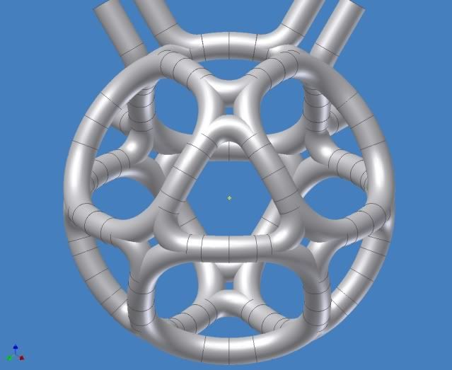
magrid configuration brainstorming

Discuss how polywell fusion works; share theoretical questions and answers.

Moderators: tonybarry, MSimon

imaginatium
Posts: 55
Joined: Mon Jan 05, 2009 10:46 pm

Post by imaginatium »

D Tibbets wrote: Another factor which may also be very significant is the shape of the cusp throat as it narrows into the cusp. The Wiffleball effect pushes these throats out and flattens them to almost a flat surface (spherical towards the center). This is what effectively decreases the leakage. The cusp itself (where opposing magnet field lines are parallel to each other is not changed.
So what happens when the basic intersection of the opposing magnetic fields are curved away from the center. The cusp throats would seem to be steeper, but possibly longer (and thus not compressed outward to the swmaller diameter of the cusp throat, ie- the Wiffleball effect is not as pronounced). What I wonder about is how this different geometry (if real) will respond to the inflating Wiffleball effect. If there is an effect, then it would be most significant with bowed (curved towards the center) magrids, or, as in the above examples, the magrids are actually curving away from the center at the corner regions. The first inward curvature may compromise the face centered point cusps, while the outward curvature may compromise the corner point/funny cusps.
Dan (which, by the way is my name too):

This would be true of the standard cuboctahedron as well. The corners are just wider throats, that are curved away from the center. I fail to see how the Wiffleball effect would be compromised.
Imaginatium (ih-ma-juh-ney-tee-uhm) -noun
Ubiquitous substance, frequently used as a substitute for unobtainium, when it is unavailable. Suitable for all purposes.

rjaypeters
Posts: 869
Joined: Fri Aug 20, 2010 2:04 pm
Location: Summerville SC, USA

Post by rjaypeters »

KitemanSA wrote:"This" is a cuboctahedron, (rectified cube / rectified octagon) just like WB6, except that what are virtual in the WB6 are real here, and vice versa.
It is my understanding when naming the geometric figures used to create a particular WB design we count the number of physical coils. "This" has eight physical coils, embedded on the faces of an imaginary octahedron.

If one wishes to include the virtual coils in the counting, then the WBs built so far are truncated cubes (six real coils with eight virtual). By that naming convention "This" would be a truncated octahedron (eight real coils with six virtual).

Can it be "just like" if what is real in one design is virtual in another design?
KitemanSA wrote:It is possible to make an octagon Polywell, as you prove with your next image (eight faces, 4 real, 4 virtual).
Regardless of terminology, the Tombo concept divides the sphere into eight regions*, four real and four virtual coils, the same numbers as a tetrahedron. Further, the Tombo enlarges the virtual coils to cover the same solid angle as the real coils. Whether that is good for confinement, I don't know, but according to happyjack27, tetrahedrons don't confine well.

*Octants, sure but that's the orthogonal nature of the design.
"Aqaba! By Land!" T. E. Lawrence

R. Peters

imaginatium
Posts: 55
Joined: Mon Jan 05, 2009 10:46 pm

Post by imaginatium »

rjaypeters wrote:Regardless of terminology, the Tombo concept divides the sphere into eight regions*, four real and four virtual coils, the same numbers as a tetrahedron. Further, the Tombo enlarges the virtual coils to cover the same solid angle as the real coils. Whether that is good for confinement, I don't know, but according to happyjack27, tetrahedrons don't confine well.

*Octants, sure but that's the orthogonal nature of the design.
RJay,

As I understand the way the terms real and virtual as used in this thread: a real coil is made from a single circuit, that ends at the same vertex as it begins.On the other hand, a virtual coil is made by using the fields of mutiple curtuuits to contain a surround a face. All the coils in the basic tombo are equilateral triangles with 2 edges from 1 circuit and the third edge from another curcuit. As such they would all be virtual.

Regarding tetrahedrons you referred to the following:
happyjack27 wrote: I've already done a (perfect) tetrahedron. pretty leaky, it seems.
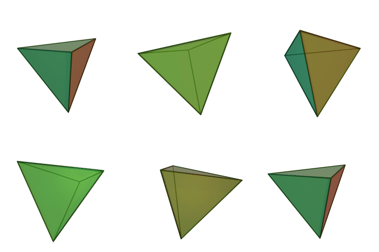
Being that you are an aeorospace engineer, I'm sure you know what a tetrahedron is, so I think your brain just mixed up the words tetrahedron and octahedron (my brain does stuff like that) . But for absolute clarity a tetrahedron is a polyhedron composed of four triangular faces, three of which meet at each vertex. :
Image


The tombo is an octahedron, not a terahedron. An octahedron is a polyhedron with eight faces, composed of eight equilateral triangles, four of which meet at each vertex.
Image
Imaginatium (ih-ma-juh-ney-tee-uhm) -noun
Ubiquitous substance, frequently used as a substitute for unobtainium, when it is unavailable. Suitable for all purposes.

KitemanSA
Posts: 6179
Joined: Sun Sep 28, 2008 3:05 pm
Location: OlyPen WA

Post by KitemanSA »

D Tibbets wrote: This illustration also leads to my opinion that the corner cusps are not strictly equivalent to point cusps, but are compound structures incorporating point and very narrow line cusp components.
Dan,
No-one really argues that a virtual magnet that is so completely a concave sided flat triangle won't approximate a confluence of line cusps. But in the core magnet design that Tombo (bless him) drew up for me, the bow sided C-O MPG with X-Cusps, the triangles are much more a convex 3D figure so the cusp at its center will be very much a point cusp. Will there be ripples in the ransverse field? Probably. Will the ripples form a cusp, I don't believe they will. And I believe that KCDodd's bag analysis supports my contention.

imaginatium
Posts: 55
Joined: Mon Jan 05, 2009 10:46 pm

Post by imaginatium »

KitemanSA wrote:
D Tibbets wrote: This illustration also leads to my opinion that the corner cusps are not strictly equivalent to point cusps, but are compound structures incorporating point and very narrow line cusp components.
Dan,
No-one really argues that a virtual magnet that is so completely a concave sided flat triangle won't approximate a confluence of line cusps. But in the core magnet design that Tombo (bless him) drew up for me, the bow sided C-O MPG with X-Cusps, the triangles are much more a convex 3D figure so the cusp at its center will be very much a point cusp. Will there be ripples in the ransverse field? Probably. Will the ripples form a cusp, I don't believe they will. And I believe that KCDodd's bag analysis supports my contention.
I presume you mean:

Image

The biggest issue I see with that design is insufficient coolant flow. How do compensate for the long paths, branching, and merging of coolant channels?
Imaginatium (ih-ma-juh-ney-tee-uhm) -noun
Ubiquitous substance, frequently used as a substitute for unobtainium, when it is unavailable. Suitable for all purposes.

D Tibbets
Posts: 2775
Joined: Thu Jun 26, 2008 6:52 am

Post by D Tibbets »

KitemanSA, If I am recalling the proper example magrid design. The x-cusp regions are bounded by four sides with 4 corners. The opposing magnetic fields would be compressed essentially to the magnet casings where they meet. On the surface this would seem to result in a line cusp of zero width intersecting the corners. But as as Bussard realized with WB4, etc, this is not how it works. The narrowest effective cusp diameter is set by the gryroradius of the electrons in that region. The upscattering of electrons increases this gyroradius for some of the transiting electrons. Also, collisions resulting in ExB drift effectively increases this line cusp loss width to several gyroradii. Bussard mentioned that up to 10 gyroradii is needed to minimize these cusp direct impact losses, though the best compromise between magnet surface impact losses in the cusps and primary confinement seems to be ~ 3-5 gyroradii. True, as the magnetic fields are compressed the magnetic field increases up to the maximum (which is the strength at the surface of the magnetic coil casing), but zero strength B field regions formed by the opposing magnets(the cusps) are also a lot closer to the surfaces. As the gyroradius is not zero, at some point as the magnet surfaces approach each other, the electrons will hit the casing. This is my understanding of why Bussard realized that the real coils (as opposed to the mathmaticically defined coils with zero magnet width and thus no surface area) had to be spaced apart . The x-cusps do not have this feature.

These intercepts are obviously tiny, but my impression from Nebel's comments about the heating of the nubs on WB7 is that these losses become significant and possibly dominant as the other cusp losses are neutralized by efficient recirculation. The system may still work adequately though, if its' other physics and engineering advantages outweigh this disadvantage .
eg: Perhaps this design might allow for greater Wiffleball trapping and thus greater densities, at the cost of greater electron losses and thus required electron current. So long as the increased electron loss rate was less that the density squared increased fusion rate, there would be a net gain- provided the engineering concerns allow the greater heating in the critical areas.

Again, this is part of the reason the Polywell fascinates me. There are many compromises that are required for the system to potentially work, and there are multiple optimizing and interacting adjustments that are possible, both in structure and knobs*.

* Knobs- include adjustments in voltage, current , pulsed or steady state, ion populations, ion injection methods, magnetic fields, relative sizes, POPS, etc.


Dan Tibbets
To error is human... and I'm very human.

KitemanSA
Posts: 6179
Joined: Sun Sep 28, 2008 3:05 pm
Location: OlyPen WA

Post by KitemanSA »

imaginatium wrote: I presume you mean:
... Correct Tombo Image...
The biggest issue I see with that design is insufficient coolant flow. How do compensate for the long paths, branching, and merging of coolant channels?
The BEST thing about this design is the maximization of coolant flow! There are two ways to do it. Either make the unit out of a set of 6 squarish and eight tringularish magnets, each with its own coolant loop OR do as ffollows:

The first thing you need to do is to look at the winding for the original MPG. It had one circuit all the way around the core. But there is a place where the circuit reaches back to the original inlet intersection. At that point, the coolant circuit can be get cut into two circuits.

Also, for this alternate method, the winding is intended to be an overlay of 4 strata of windings so that there are FOUR coolant circuits thru each leg of the unit. It will be properly cooled, believe me.

Oh, and by the by, the coolant circuit does NOT have to be the same as the electrical circuit so the coolant can be put thru the entire set of conductors in one loop while the electrons go round and round and round.

KitemanSA
Posts: 6179
Joined: Sun Sep 28, 2008 3:05 pm
Location: OlyPen WA

Post by KitemanSA »

D Tibbets wrote:KitemanSA, If I am recalling the proper example magrid design. The x-cusp regions are bounded by four sides with 4 corners. The opposing magnetic fields would be compressed essentially to the magnet casings where they meet. On the surface this would seem to result in a line cusp of zero width intersecting the corners. But as as Bussard realized with WB4, etc, this is not how it works. The narrowest effective cusp diameter is set by the gryroradius of the electrons in that region. The upscattering of electrons increases this gyroradius for some of the transiting electrons.
Which is the reason for the hole in the X cusp. You do get that if the squares are "North in", the triangles are "North out" adn the X-cusps are null fields with the metal far enough away to be shielded, right?

icarus
Posts: 819
Joined: Mon Jul 07, 2008 12:48 am

Post by icarus »

The "X-cusps" are a bad idea. They create a null point in the magnetic field that will attract charged particles and then stick a whole bunch of metal in the same location, I haven't seen any analysis or experiments to say that isn't the case. It is just bizarre anybody is considering them.

rjaypeters
Posts: 869
Joined: Fri Aug 20, 2010 2:04 pm
Location: Summerville SC, USA

Post by rjaypeters »

Here is a collection of four coils:
Image

They are arranged on the four faces of a tetrahedron: Trimetric, Top and Right views
Image Image Image


Image
Front View

If the corners are lopped off we have a truncated tetrahedron (Trimetric view):

Image
There are four of the truncated regions which "host" virtual coils.

rjaypeters wrote:Topologically, the closest coil configuration to a spherized Tombo is a tetrahedron which has terrible confinement (according to happyjack27). Let's be careful about loving the spherized Tombo too much before a simulation gives an idea about performance.
I've never said the Tombo was a tetrahedron.
"Aqaba! By Land!" T. E. Lawrence

R. Peters

rjaypeters
Posts: 869
Joined: Fri Aug 20, 2010 2:04 pm
Location: Summerville SC, USA

Post by rjaypeters »

Regarding octahedra, it might be useful to compare these pictures: The first two have eight physical coils.

Image Image

The immediately previous with four coils removed:
Image

How is the last different from a tetrahedron? It has four physical coils and four virtual coils.

Then there is this version of the Tombo:
Image
How are the last two different?

And compare with the tetrahedron: Image and count the physical "coils" where the current runs around in one orientation and virtual coils where the current runs around in the opposite orientation.

[edit]And how many real and virtual coils does this "single-coil" design have?Image
"Aqaba! By Land!" T. E. Lawrence

R. Peters

KitemanSA
Posts: 6179
Joined: Sun Sep 28, 2008 3:05 pm
Location: OlyPen WA

Post by KitemanSA »

rjaypeters wrote:Here is a collection of four coils:
...
They are arranged on the four faces of a tetrahedron: Trimetric, Top and Right views
..............
If the corners are lopped off we have a truncated tetrahedron (Trimetric view):
..........
There are four of the truncated regions which "host" virtual coils.
Please folks, stop thinking "truncated" and think EITHER "fully truncated" or rectified which are equivalent terms. They are the only way to get Polywell forms similar to the original patent. If you start with a tetrahedron and fully truncate it you get an octaheron which is the true Polywell form all your images approximate.

imaginatium
Posts: 55
Joined: Mon Jan 05, 2009 10:46 pm

Post by imaginatium »

rjay, you are completely missing the point, which is that happyjack27's statement does not apply to tombos . The reason rectified tetrahedrons have bad containment has very little to do with the number of faces; it has to do with the degree of quasi-spherity of the magnetic fields forming the Wiffleball, and the acutness of the interior angles at the cusps. a spherized tombo's is much more quasi-sprerical than a rectified tetrahedron, with less accute angles at the cusps.

Edit: I reread your posts and figured out you are comparing a rectified (not truncated) tetrahedron to a flat edged tombo, instead of a spherized tombo (I was confused by context).
Last edited by imaginatium on Mon Feb 21, 2011 2:42 am, edited 2 times in total.
Imaginatium (ih-ma-juh-ney-tee-uhm) -noun
Ubiquitous substance, frequently used as a substitute for unobtainium, when it is unavailable. Suitable for all purposes.

imaginatium
Posts: 55
Joined: Mon Jan 05, 2009 10:46 pm

Post by imaginatium »

KitemanSA wrote:
D Tibbets wrote:KitemanSA, If I am recalling the proper example magrid design. The x-cusp regions are bounded by four sides with 4 corners. The opposing magnetic fields would be compressed essentially to the magnet casings where they meet. On the surface this would seem to result in a line cusp of zero width intersecting the corners. But as as Bussard realized with WB4, etc, this is not how it works. The narrowest effective cusp diameter is set by the gryroradius of the electrons in that region. The upscattering of electrons increases this gyroradius for some of the transiting electrons.
Which is the reason for the hole in the X cusp. You do get that if the squares are "North in", the triangles are "North out" adn the X-cusps are null fields with the metal far enough away to be shielded, right?
The line cusps you need to worry about are the one diagonally through the metal of corners where the coils split and merge.
Imaginatium (ih-ma-juh-ney-tee-uhm) -noun
Ubiquitous substance, frequently used as a substitute for unobtainium, when it is unavailable. Suitable for all purposes.

rjaypeters
Posts: 869
Joined: Fri Aug 20, 2010 2:04 pm
Location: Summerville SC, USA

Post by rjaypeters »

KitemanSA,

I know about some of the relationships between tetrahedrons and octahedrons, I was showing at least some of them to another correspondent who thinks I can't tell the difference.

All was doing was counting the physical and virtual coils. The closest analog to the single-coil I put up a few days ago, which had a simulation result I have only read about as a passing reference, is a straight tetrahedron (four physical coils and four virtual coils).

My comment was to be careful about putting too much faith in any core which has fewer physical coils absent an engineering analysis or test. The Tombo (which is even closer to the aforementioned single-coil) hasn't been through any analysis I have seen.
Imaginatium wrote:The reason rectified tetrahedrons have bad containment has very little to do with the number of faces; it has to do with the degree of quasi-spherity of the magnetic fields forming the Wiffleball, and the acutness of the interior angles at the cusps. Tombo's octahedron is more quasi-sprerical than a rectified tetrahedron, with less accute angles at the cusps, and if you spherize it, much more so.
Where are the test data or analysis results which support these assertions?
"Aqaba! By Land!" T. E. Lawrence

R. Peters

Post Reply