Near Spherical Magrid

Discuss how polywell fusion works; share theoretical questions and answers.

Moderators: tonybarry, MSimon

D Tibbets
Posts: 2775
Joined: Thu Jun 26, 2008 6:52 am

Post by D Tibbets »

ladajo wrote:In WB6 & 7 the current flows are opposite in each adjacent coil.
Yes, but the polarity of the fields are still the same (N- pole points in in both coils (or visa virsa). The same applies to the curved ends of the coils that make up the intermittent coil lengths that lead to the corner virtual cusps. But if you trace the current through these sections to complete a virtual coil, the current is reversed compared to the real coils so the (virtual ?) magnetic field pole is reversed. This virtual coil description is perhaps useful for explaining why the corner coil may act as a near point cusp, if you accept this assumption. Otherwise, it confuses me. Did Bussard ever describe the corner cusps in this fashion? Are the corner cusps better pictured as an X (or triangular) cusp with the cusp intercepting the metal were the nubs were in WB6?

Dan Tibbets
To error is human... and I'm very human.

D Tibbets
Posts: 2775
Joined: Thu Jun 26, 2008 6:52 am

Post by D Tibbets »

KitemanSA wrote: .....

I do not believe that Dr. B would have liked this design as it has very long linear cusps and everything I've read by Dr. B suggests he thought linear cusps were bad. Indeed, HIS next unit would have had effectively NO linear cusps instead of the two-diameters worth of this design.

....
I think the 4 grid bowed design has the same linear or funny cusp lengths as WB 6. The difference is that they flow around 4 oval magnets instead of 6 round magnets ( the total circumference of the coilsis ~ the same).
The difference is that they spread into / through 2 corners instead of 8. It boils down to which contributes the most to losses, the corners or the funny cusps. If the funny cusps strongly dominate, the net results should be ~ same. If the corner cusps contribute a significant amount to the losses, then there should be a gain.

I'm more worried about what the inward bowing of the magnet coil does to the point cusps in the middle of the coils. The center of the cusp may be a little bigger ( perhaps to the extent that the point cusp area in this 4 grid design matches the area in the 6 grid WB6 design.
But, the throat into the cusp and it's response to the Wiffleball derived pinching may be different.

A further warping of the coils beyond that that might be used to manage the corner cusp field geometry might be useful.
The coil case could be wider in the direction away from the corner cusps (on the top and the bottom, while the case could be wider in the direction towards the center point cusps in the middle of the coil. This would result in a complex can shape but the internal volume would be the same and increased in both regions. This would allow more windings / insulation, etc . without increasing the overall radius of the coil. There might be other advantages that would require careful study to evaluate.

Dan Tibbets
Last edited by D Tibbets on Fri Oct 08, 2010 1:23 am, edited 1 time in total.
To error is human... and I'm very human.

KitemanSA
Posts: 6179
Joined: Sun Sep 28, 2008 3:05 pm
Location: OlyPen WA

Post by KitemanSA »

icarus wrote:
I do not believe that Dr. B would have liked this design
Reference?
Valencia Paper, patent, WB6 final report. Maybe I've been mis-reading them, but I don't think so.

icarus
Posts: 819
Joined: Mon Jul 07, 2008 12:48 am

Post by icarus »

That's a ridiculous amount of extrapolation from one paper to a whole class of possible magnet configurations. What's the exact 'design criteria' you are using? Page, paragraph, sentence? Is it quantifiable?

'I don't think he would have liked ...' is just voodoo physics/engineering.

rcain
Posts: 992
Joined: Mon Apr 14, 2008 2:43 pm
Contact:

Post by rcain »

KitemanSA wrote: I do not believe that Dr. B would have liked this design as it has very long linear cusps and everything I've read by Dr. B suggests he thought linear cusps were bad. Indeed, HIS next unit would have had effectively NO linear cusps instead of the two-diameters worth of this design.

But who knows. Try it and find out!
I was thinking the same, about line cusps at a least (if i count right we have replaced the corner (cross/funny) cusps with line cusps, and got rid of two point (face) cusps - bu maybe i'm not counting right, its late for me..)

in any case, the line cusps have appeared, so i was wondering is there some easy way we can extrapolate/estimate the 'relative ion/electron capture rates' (leakage rate) associated with each type of cusp, and try and draw some conclusions about benefit/debenefits of the config from the model first.

gotta be some fairly simple dimensional (power) equation / inequality we can derive.

anyone bold enough?

@icarus - easy there! Kite only suggested 'he thought... ' bussard might have thought it a bad idea; expressing his 'opinion'. I was hoping perhaps Tom Ligon or MSimon or someone might have a few 'anecdotal facts' to inject on the question.

KitemanSA
Posts: 6179
Joined: Sun Sep 28, 2008 3:05 pm
Location: OlyPen WA

Post by KitemanSA »

icarus wrote: That's a ridiculous amount of extrapolation from one paper to a whole class of possible magnet configurations. What's the exact 'design criteria' you are using? Page, paragraph, sentence? Is it quantifiable?
The quantification is in the Valencia paper, do you need help reading it? I've already admitted that I might! ;)

Dr. B. compares point and line cusps in the paper with formulea and numbers and seems to conclude that line cusps are much more leaky than point cusps. He then stated he wanted to do an experiment with a WB7 that included square plan form magnets. Such magnets should have much shorter line-like cusps (indeed approaching none at all IMHO).
icarus wrote: 'I don't think he would have liked ...' is just voodoo physics/engineering.
Ung-gawah, melt-wing. Who do that spew-do that you do so well?

Tis neither physics nor engineering, tis my partially informed opinion. How bout discussing the substance of the opinion rather than your emotional reaction to the opinionator?

D Tibbets
Posts: 2775
Joined: Thu Jun 26, 2008 6:52 am

Post by D Tibbets »

The line like cusps were already there in WB 6. All of the edges are line cusps in effect. They are modified somewhat as they cross each other at the corners of WB6. Describing these areas as virtual magnets may indicative that these areas are less leaky per unit of volume, but they are still much larger than the linear cusps between the closely spaced magnets. Bussard referred to these line cusps as "funny cusps" in his models where the magnets were considered to be infinity small lines with infinity small spaces (cine cusp widths) between them. It was the realization of the unreality of this that lead to the development of WB6 with spaced magnets. The leakage through these was recognized, thus the need for several electron gyroradii, so that recirculation could correct for these otherwise unavoidable and unacceptable losses. The combination of the close magnet placement, and especially Wiffleball effect and recirculation that together allows for acceptable losses here and elsewhere.
The question is what these cusps contribute to the total losses compared to the corners. Apparently, it is not trivial, otherwise the concerns about the nubs would not exist. And as I said, the line like cusp lengths in the 4 grid bowed near sphere would be ~ the same. But, the corner portions would be 1/4th. The addition sphericity without multiplying the corner cusps number and line cusp lengths (?) of a higher order polyhedron would help, Unless the relative loss contribution of the corner cusps (or if you prefer the corner virtual magnets) is much less that the remaining linear cusp portions.
The way Bussard, etel described cusp losses in the 2008 patent application, it sounds like he clumped the corner cusps and their extension to the nubs as a single cusp, as he described these losses compared to the true point cusps. He did not differentiate into corner and linier portions of the cusps.

In effect, in WB6 you have 8 corner cusps with 3 narrow legs that extend to the nub interconnect region of the magriid magnets. With the bowed 4 grid design you have 2 corner grids with 4 narrow legs that extend twice as far before reaching the nubs. How do their losses compare?

Dan Tibbets
To error is human... and I'm very human.

KitemanSA
Posts: 6179
Joined: Sun Sep 28, 2008 3:05 pm
Location: OlyPen WA

Post by KitemanSA »

D Tibbets wrote:The line like cusps were already there in WB 6. All of the edges are line cusps in effect. They are modified somewhat as they cross each other at the corners of WB6. Describing these areas as virtual magnets may indicative that these areas are less leaky per unit of volume, but they are still much larger than the linear cusps between the closely spaced magnets. Bussard referred to these line cusps as "funny cusps" in his models where the magnets were considered to be infinity small lines with infinity small spaces (cine cusp widths) between them. It was the realization of the unreality of this that lead to the development of WB6 with spaced magnets.
You and I may be talking at cross purposes. My usage is as follows:
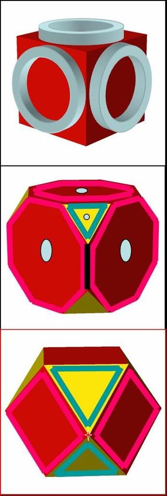
In the graphic below, the line like cusps are where the black lines are (only one shown) in the middle section. The yellow triangle of the middle section is the virtual magnet. It develops a point cusp at the center (pale blue dot) like the red real magnet; probably not as perfect a point, but still not a line. The "funny cusp" is where that little 4 pointed star is, at the vertex, on the bottom section.

As a reasonable approximation from the middle section, the line cusps cover about 12/36ths of the total magnet boundary in WB6 but 36/36ths of the total boundary in the proposed configuration. That suggests to me that there will be a LOT more leakage in the ... "wedge"(?) configuration, not even considering the PRIME question of whether the configuration can provide anything LIKE a wiffleball effect.

None-the-less, it would be interesting...


Image

rjaypeters
Posts: 869
Joined: Fri Aug 20, 2010 2:04 pm
Location: Summerville SC, USA

Post by rjaypeters »

What about these? I call them "Tibbets Triple."

See here:

"http://www.facebook.com/album.php?aid=1 ... e0097c7730"

Three line cusps, two corner cusps. Each bent ring (pipe) uses a 1.1 to 1 ratio, approximately, height to width of the original ellipse used to project the pipe.

P.S. I'm no magnetic theorist, just playing with geometry. Try to go easy on me.

EDIT: Here are pictures, directly.

Image Image Image
Last edited by rjaypeters on Tue Oct 26, 2010 7:50 pm, edited 1 time in total.
"Aqaba! By Land!" T. E. Lawrence

R. Peters

D Tibbets
Posts: 2775
Joined: Thu Jun 26, 2008 6:52 am

Post by D Tibbets »

KitemanSA, I think our termonology is not too far apart .The corner have soome point like chariteristics, thanks to the vertual or imaginargy ring like current through the true magnets in this area. Where they naroow down, at some arbitrary point you could consider the rest as the remaining line or funny cusps. But, the corner cusps are not true point cusp. The patent application mentions that the losses were ~ 5-7 times the true face centered point cusps. The quetion is how much of this loss is within the area that could be subdivided into the corner or vertual point cusp, and how much is from the remaining portion between the real magnets ( to the region of the nubs in WB6.
Recirculation may allow for similar input power requirements irregardless. But, if primary containment of the electrons are improved, then I guess that the Wiffleball trapping factor and thus internal density could be raised. The second question is if the confinement is not improved or worsened much, could the greater sphericity be valuable on its own. To get the same sphericity with a higher order polyhedria would (I think)add to the line/ funny cusps lengths and possibly the corner/ vertual point like cusp areas.

Dan Tibbets
To error is human... and I'm very human.

rjaypeters
Posts: 869
Joined: Fri Aug 20, 2010 2:04 pm
Location: Summerville SC, USA

Post by rjaypeters »

"Aqaba! By Land!" T. E. Lawrence

R. Peters

Randy
Posts: 82
Joined: Mon Sep 20, 2010 5:40 am
Location: Texas

Post by Randy »

KitemanSA wrote: ...
If someone has a big enough, good enough chamber and power supply, I'd be willing to wind a number of potential designs. I'm thinking about 30cm radius but only 16ish turns.

Anyone? Don't all answer at once! ;)
Hi Kiteman,
I know you’ve been looking for parts to make a prototype magrid testing platform.
If someone will donate a suitable vacuum chamber then I’m willing to donate some parts that I ripped out of an old “Reliance 40HP 480Volt three-phase AC variable speed motor drive”. You could use these (expensive) parts to make a high voltage capacitor bank pulse-discharge power source. Normally capacitor discharge sources are low voltage types for electrical (shock) safety reasons and they are designed to drive low inductance, low resistance, and high current loads.
But with a higher voltage (450VDC) capacitor bank power source you could pulse-drive a set of magrid coils that have a much higher inductance (more wire turns per coil using smaller diameter wire) at a lower peak current and still achieve a suitable pulsed B-Field magnitude (in Teslas) using a much smaller overall power source package size. In this case, I would not use coil wires that had an insulation rating of less than 1000 volts. Also, I wouldn’t use standard varnish-coated magnet wire – too much risk of mechanical damage to the thin varnish coating. I’d tend to lean more toward newer high voltage and thicker insulated Teflon coated wires for the coils.

I have four 2400uF 450VDC electrolytic capacitors and five industrial Darlington power transistors:
Image
Image
Image
Image

Here’s an image of one of the power transistors I used in a simple high power adjustable linear voltage regulator (0 to 36VDC). The upper left transformer is only used for up to 4.0 amp testing. But I can hook this thing up to my DC welder as a power source for supplying adjustable (0 to 36VDC) at high current (~ 40 amp) testing:
Image

The power transistors are rated at 600VDC and can handle about 40 amps each. But you can parallel the transistors to drive (dump) a 450VDC 200Amp pulse through the magrid coils. I’m willing to wire up the power source and pre-test it for you if you can find a suitable vacuum chamber.

Note: Physical contact with a 450VDC charge from a 9600uF capacitor bank will KILL YOU! This rig would definitely not be a toy. So please be totally aware and exceptionally careful with its use… I will put it all inside a grounded metal ‘Hoffman box’ enclosure and supply you with ample schematics and safety instructions should you decide to use it.

~Randy
D Tibbets
Posts: 2775
Joined: Thu Jun 26, 2008 6:52 am

Post by D Tibbets »

I'm not sure this type of supply would work. It depends on how fast this pulse is. You probably need 10's of milliseconds to allow for other systems timing (gas puffer, electron guns, etc) to be accommodated, even with fast switches. In WB 6, etc mention is made of the magnets being powered for up to several seconds before heat became a concern. Certainly smaller wires would increase the amp-turns. If the timing could be better controlled, magnet currents of perhaps 10-100 ms might have been possible, with corresponding ~ 10-100 times the amp turns before heating limits were reached*.

Batteries work well. A constant high current can be delivered. I don't know how the batteries were arranged in WB6. Were they all parallel (12V) of combination of parellel and series? 10 batteries in series would deliver 120V.

*Within limits. As the wire diameter decreases, the insulation contribution to the total diameter/ volume of each wire increases.

Dan Tibbets
To error is human... and I'm very human.

D Tibbets
Posts: 2775
Joined: Thu Jun 26, 2008 6:52 am

Post by D Tibbets »

From the Magrid Configuration Brainstorming (page 25) thread-
KitemanSA wrote:But an octahedral Polywell is one of the basic designs in Dr.B's patent and they don't have exactly opposing magnets. Indeed, the magnet opposite an in magnet is an out magnet, but the octahedral polywell is anticipated to work just fine.

I think your recent train of thought needs re-thinking. There is no reason to believe that identical opposing magnets are needed. In my understanding, what is needed is the vector summation to zero, and that can be had with many different configurations.

I'm uncertain. If KitemanSA's contention is true, then my first iteration of a spherical bowed magrid made up of three separate magnets should work. Compared to the 4 magnet design, the advantages would be fewer line cusps, only three center point cusps, and possibly less deformation of the center point cusps.

Image

Dan Tibbets
Last edited by D Tibbets on Mon Oct 18, 2010 1:41 am, edited 1 time in total.
To error is human... and I'm very human.

GIThruster
Posts: 4686
Joined: Tue May 25, 2010 8:17 pm

Post by GIThruster »

Why do you need vacuum to test various magrid configurations? The magnetic permeability of air is so close to vacuum, that one would think if all you're going to do is test configs, and not run fusion experiments (or is this required to "test configurations"), that you could do without all the pain and expense of vacuum.

Seems you could test the configurations in ways other than running fusion experiments. IIRC, there's a sheeting that has ferro-fluid sandwiched between a pair of flexible plastic sheets, and by repeatedly placing them inside the magrid and firing up the coils, you could do a very complete 3D analysis of the fields generated.

I think I actually have one of those sheets around somewhere. They're cheap. Certainly cheaper than all the plumbing for a vacuum system and they're completely reusable. They won't tell much about magnitude though. For that, you'd certainly find it easier to run a spherical magnetic field sensor than a vacuum chamber.

But I do have a decent roughing pump sitting idle I will donate if vacuum is the only way to go.
"Courage is not just a virtue, but the form of every virtue at the testing point." C. S. Lewis

Post Reply