magrid configuration brainstorming
-
rjaypeters
- Posts: 869
- Joined: Fri Aug 20, 2010 2:04 pm
- Location: Summerville SC, USA
You’re talking about the magnetic field produced by current flowing through a coil of wire.WizWom wrote: First: magnetic field of a loop (of which a solenoid is a special case) is just
F1) {number of turns} * current * mu-nought
inside the loop, outside it is reduced by 2 * pi * d^2. If there are multiple loops, you just vector sum the effect of all of them at any point you choose. The formula acquires a binormal vector from the position vector to the loop and the plane of the loop exit (I hope you have had vector calculus and understand that)...
Everything else you talked about concerned how the motion of charged particles is affected under the influence of externally generated electric and magnetic fields.
I wasn’t talking about how electrons move around in fields.
Back to your first point ‘the magnetic field of a current carrying coil of wire’. Let’s talk about that.
Suppose you took six coils and arranged them about the faces of a cube (as in a standard six-coil magrid design) what is it, the WB6 I believe? Energize the six coils such that each coil’s north pole faces toward the core of the magrid. Now, you have six sets of magnetic field lines going into the center of the magrid. Where do these magnetic field lines come out of the magrid?
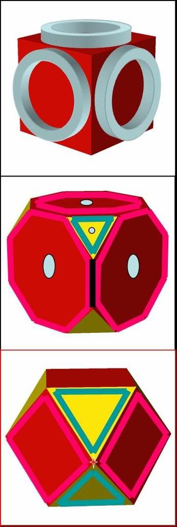
If you place six coils on a cube as shown in the top section of this graphic, the field will come out from between the coils along the edge of the cube and thru the yellow triangular sections as shown in the middle section. (Yes, I know, the coil cases are shown square cross section but powerpoint doesn't have a torus drawer! The middle figure is a "truncated" cube. But those edges represent line-like cusps which Dr. B seemed to dislike. As a result, the first new machine he wanted to build after duplicating WB6 was to be WB7, a rectified cube like the bottom section with "square plan form" magnets. The red would be in and the yellow out. In the bottom section the pinkish line would represent the real "square plan form" North-In magnet and the teal line would be a virtual "North-Out" magnet. But it could be a real magnet with no significant change in overall field except in detail at the vertices.Randy wrote: Back to your first point ‘the magnetic field of a current carrying coil of wire’. Let’s talk about that.
Suppose you took six coils and arranged them about the faces of a cube (as in a standard six-coil magrid design) what is it, the WB6 I believe? Energize the six coils such that each coil’s north pole faces toward the core of the magrid. Now, you have six sets of magnetic field lines going into the center of the magrid. Where do these magnetic field lines come out of the magrid?
So, for ANY magrid design you will have a set of faces where the magnetic field goes inward and a set of faces where the magnetic field comes outward. In this respect the octahedron configuration of which I’ve spoken earlier is no different than a WB6 (truncated cube) or WB7 (rectified cube). The only difference is that all eight coils are real triangular plan-form coils and the polarity of adjacent coils alternates.
This is the only point I was trying to communicate.
~Randy
This is the only point I was trying to communicate.
~Randy
True provided one understands there is a difference between "all real" and "real/virtual" at the vertices, and that WB7 being a rectified cube only applies to Dr. B's original plan. Dr. N's WB7 was a truncated cube like the WB6.Randy wrote:So, for ANY magrid design you will have a set of faces where the magnetic field goes inward and a set of faces where the magnetic field comes outward. In this respect the octahedron configuration of which I’ve spoken earlier is no different than a WB6 (truncated cube) or WB7 (rectified cube). The only difference is that all eight coils are real triangular plan-form coils and the polarity of adjacent coils alternates.
This is the only point I was trying to communicate.
~Randy
-
happyjack27
- Posts: 1439
- Joined: Wed Jul 14, 2010 5:27 pm
edges vs. planes and electric / magnetic fields.
"the polarity of adjacent coils alternates" - i think this is unclear. each "edge" is a cluster of wires wherein the current is all going the same direction. notice that means the current "rotates" around each "plane" in either a clockwise or counter-clockwise direction. red planes are clockwise, yellow, counter-clockwise (or vice-versa).Randy wrote:So, for ANY magrid design you will have a set of faces where the magnetic field goes inward and a set of faces where the magnetic field comes outward. In this respect the octahedron configuration of which I’ve spoken earlier is no different than a WB6 (truncated cube) or WB7 (rectified cube). The only difference is that all eight coils are real triangular plan-form coils and the polarity of adjacent coils alternates.
This is the only point I was trying to communicate.
~Randy
since magnetic field are transverse to current, that means that said currents induce magnetic field lines that go "in" on one plane-color and "out" on another.
due to lorenz' law, electrons will follow these field lines in one direction, while protons will follow it in the other. being orders of magnitude lighter per unit charge than protons, electrons are going to be orders of magnitude faster and thus are going to win the competition for these recirculating paths. thus those different colored faces represent electron "in" points and "out" points for recirculation.
-
happyjack27
- Posts: 1439
- Joined: Wed Jul 14, 2010 5:27 pm
There has been a bit of debate as to whether the electrons actually get far enough from the face to actually make it around the arc. Remember, there is a high positive voltage on the MaGrid that slows and returns the electrons quickly. To many on this forum, "recirculate" merely means "stop and come back in along the same field line".happyjack27 wrote:...so to get an idea of the induced current, just picture half-arcs connecting each face to the neighboring faces of opposite color. those are the recirculating paths for electrons. protons just get trapped inside by repulsion with the recirculating electrons.
-
happyjack27
- Posts: 1439
- Joined: Wed Jul 14, 2010 5:27 pm
good point. perhaps an experiment could help resolve the exact proportions. e.g. just bisect the "arcs" with metal sheets and measure the voltage w/reference to ground on them from the electrons they catch.KitemanSA wrote:There has been a bit of debate as to whether the electrons actually get far enough from the face to actually make it around the arc. Remember, there is a high positive voltage on the MaGrid that slows and returns the electrons quickly. To many on this forum, "recirculate" merely means "stop and come back in along the same field line".happyjack27 wrote:...so to get an idea of the induced current, just picture half-arcs connecting each face to the neighboring faces of opposite color. those are the recirculating paths for electrons. protons just get trapped inside by repulsion with the recirculating electrons.
additionally then the angle of the sheets could be varied to see just how far down the arc electrons go before turning around. come to think of it, it seems a lot of useful data can be gathered from just such a simple setup.
Perhaps Nonmagnetic floating plates, or rather one plate that is moved between tests, might indicate a voltage/ and or current that reflects the electrons reaching it through the cusp. But, I suspect it is complicated. Anything near the cusps will change the dynamics. Bussard said the electron guns need to be ~ 1/2 the raduis (or was it the diameter?) from the cusp to avoid undesirable interference and that too much distance would compromise electron injection. A lot of head scratching would be needed to figure out if you are measuring cusp behavior or only the interaction from the plates. It is sort of like quantum mechanics. You cannot measure the system without introducing outside effects.
Dan Tibbets
Dan Tibbets
To error is human... and I'm very human.
I've wondered if these opposing magnets with the same shape but inverted layout (triangle with base facing the opposite hypotenuse (peak)) would allow for symmetrical opposing magnetic fields which I'm assuming is needed for resistance against the expanding Wiffleball pressure. Would these resultant fiends that would bulge asymmetrically, possibly distorting the cusps and / or resulting in local concave fields the center. In other words would they compromise the ability of the Wiffleball to raise the internal pressure, or harm stability due to concave magnetic distortions.Randy wrote:Yes – yes, I see what you’re saying: “Why not make the virtual poles (about the triangular faces) real coils as well?” ‘tombo’ does indeed make good 3-D graphics!KitemanSA wrote:Good question. At the present only the MPGs have had this plan-form. I have read that they were amongst the only other machines to do fusion, so perhaps the condition is of LESS importance in this design than in a round plan-form machine like WB6.Randy wrote: Is this an issue?
Personally, I like the bow-legged real-real version of this design. This one!Kudos to tombo! marvelous graphic!
As I mentioned earlier my concern about the B-field through the triangular faces of the cuboctahedron being almost double that through the square faces. I thought that this phenomenon might introduce more inductance into the electric circuit of the magnet coils.
Coil inductance is a big issue with prototype magrid configurations because they will almost always be of the pulsed current type (large capacitor-bank discharge test platforms).
This led me to favor the octahedron (eight-coil) configuration. But I did a quick double-check analysis and discovered that even though the B-field through the triangular surfaces is almost double that through the square faces, this does not affect the overall inductance of the electric circuit. My reasoning follows:
Total coil flux linkage (flux) = B * Area.
L(inductance) = Nturns * total coil flux linkage (flux) / i.
My previous analysis shows that for the triangular faces the B-field magnitude increases in the same proportion as the decrease in the area of the triangles as compared to the total surface area of the cuboctahedron. Thus causing no net change in the [Total coil flux linkage (flux) = B * Area] through the triangular faces. Therefore the L(inductance) of the circuit is not affected by this phenomena.
This observation shows that (as far as electric circuit inductance is concerned) the six coil cuboctahedron square plan-form magrid configuration is likely a better design than an eight coil triangular plan-form octahedron configuration because it only features six coils, thus introducing less overall coil circuit inductance.
Kiteman, I definitely see why you like the bow-legged real-real design.
The KISS (Keep It Simple Stupid) paradigm has never failed me. So for simple prototype designs I believe the “squared” cuboctahedral design is the most desirable configuration to work with. It can’t be much more difficult to fabricate six square plan-form coil spools than six round plan-form coil spools. i.e., the six coil cuboctahedron square plan-form magrid configuration. As posted by you earlier:
…This is likely the best simple magrid configuration for prototype construction.
~Randy
I have heard Bussard's comments about square coils, but I had assumed that they were arranged like a box or cube that would be less truncated than the round coil WB6.
D Tibbets
To error is human... and I'm very human.
Check out Figure 8 (page 5) from Dr. B's 1989 patent. This is it.D Tibbets wrote:I have heard Bussard's comments about square coils, but I had assumed that they were arranged like a box or cube that would be less truncated than the round coil WB6.KitemanSA wrote:
D Tibbets
http://patft.uspto.gov/netacgi/nph-Pars ... =4,826,646